Apparatus and method for downhole steam generation and enhanced oil recovery

a technology of enhanced oil recovery and apparatus, which is applied in the direction of tunnel/mine ventilation, fluid removal, insulation, etc., can solve the problems of inability to implement thermal completions of eor in wells that were not completed with such high temperature resistant materials, and inability to provide economic solutions in in-situ processes to date. achieve the effect of reducing the amount of heat los

Active Publication Date: 2010-07-22
ESPRESSO CAPITAL LTD
View PDF32 Cites 45 Cited by
  • Summary
  • Abstract
  • Description
  • Claims
  • Application Information

AI Technical Summary

Benefits of technology

[0012]Water is also injected into the target zone above the combustion cavity, which flow or permeate laterally into the reservoir adjacent the wellbore. In the reservoir, the water acts to cool the reservoir adjacent the wellbore, decreasing the amount of heat lost to the overburden. At an interface, the water and hot combustion gases combine to create a steam and gaseous drive front.
[0013]Further, the injection of water adjacent the wellbore also cools the cased wellbore, protecting the casing against the heat from the steam and hot combustion gases. Accordingly, the present invention is not limited to use only in thermally completed wells and can be implemented at any cased wellbore, whether or not the wellbore was completed for thermal EOR.

Problems solved by technology

Thermal methods of EOR can only be implemented in wells that have been completed for thermal completions.
Wells that were not completed with such high temperature resistant materials cannot implement thermal completions for EOR.
In-situ processes to date have not successfully provided economic solutions and have not resolved issues of temperature management, corrosion, coking and overhead associated with existing surface equipment.

Method used


Image

  • Apparatus and method for downhole steam generation and enhanced oil recovery
  • Apparatus and method for downhole steam generation and enhanced oil recovery
  • Apparatus and method for downhole steam generation and enhanced oil recovery

Examples


Embodiment Construction

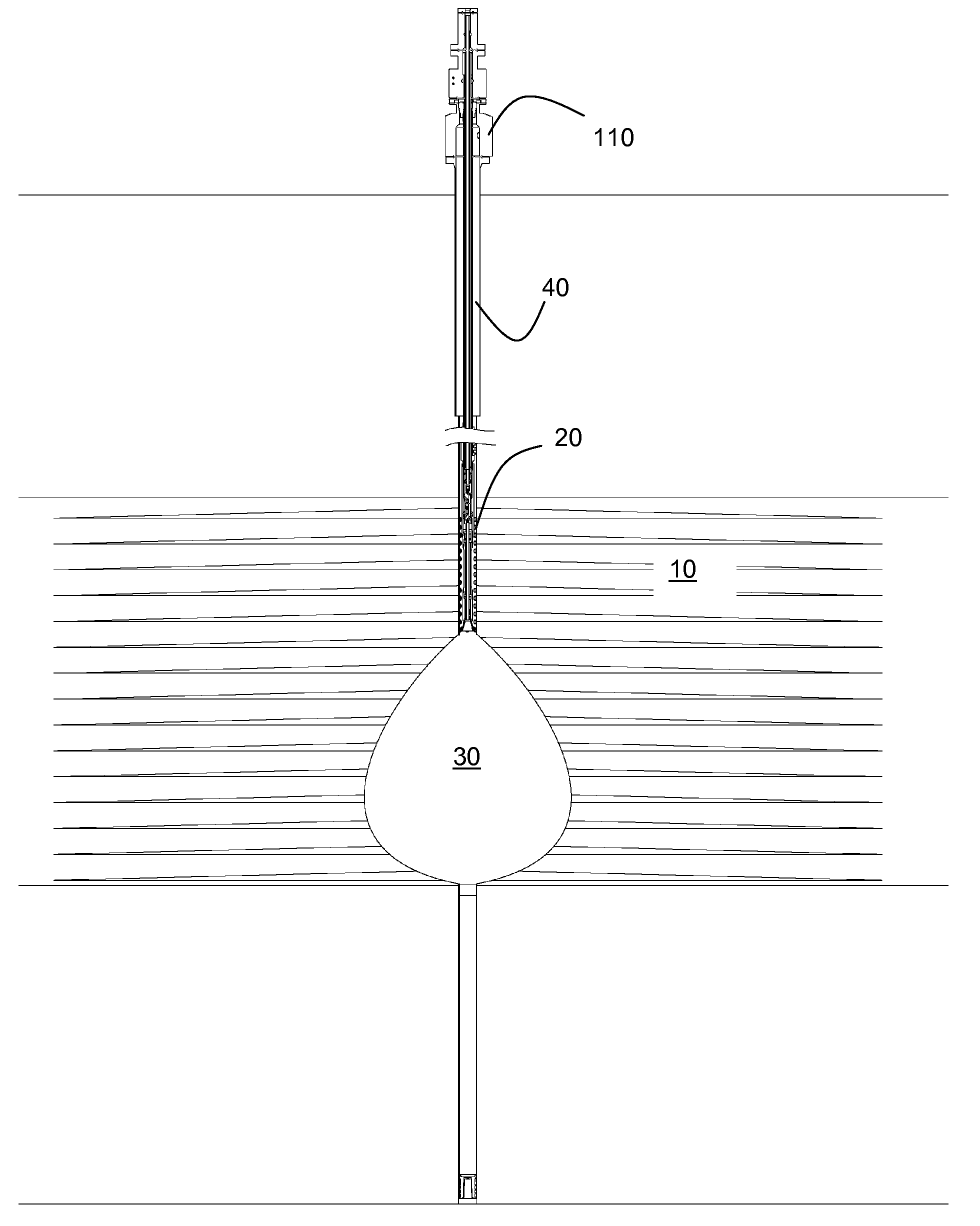
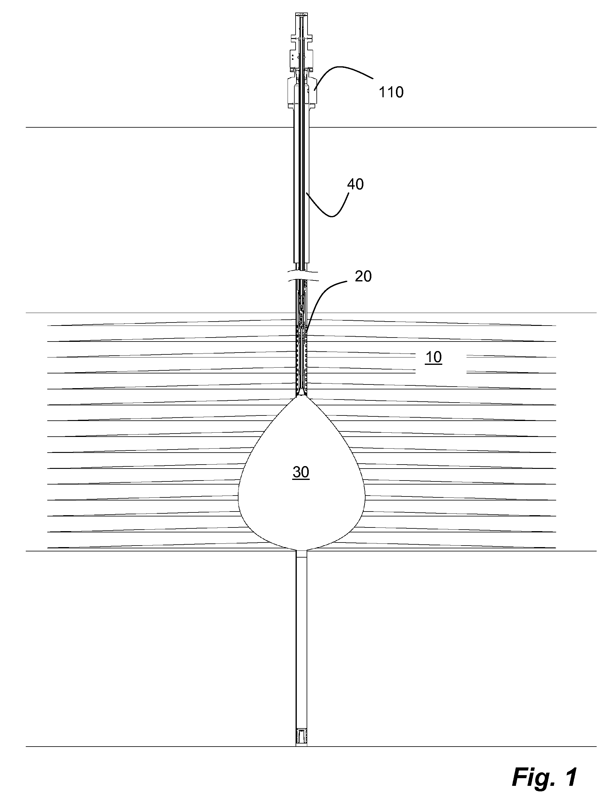
[0037]As shown in FIG. 1, a thermal process utilizes a downhole production of heat, steam and hot combustion gases (primarily CO, CO2, and H2O) to best effect for the recovery of residual or otherwise intractable hydrocarbons from a hydrocarbon reservoir 10. A burner assembly 20 initially creates a combustion cavity 30 and then creates and sustains the creation of hot combustion gases, such as CO, CO2, and H2O. Addition of water to the reservoir 10 above the combustion cavity 30 results in the production of a steam drive front. The steam and hot combustion gases combine to create a steam and gaseous drive front.

[0038]With further reference to FIGS. 1, 2B, 3, 4 and 13, apparatus for implementing such a process comprises a burner assembly 20 at a downhole end of a main tubing string 40 and one or more additional tubing strings. The main tubing string 40 and other tubing strings form a plurality of discrete fluid passageways for supplying the burner assembly 20. As shown in FIG. 4, the...


PUM


Abstract

A burner with a casing seal is used to create a combustion cavity at a temperature sufficient to reservoir sand. The burner creates and sustains hot combustion gases at a steady state for flowing into and permeating through a target zone. The casing seal isolates the combustion cavity from the cased wellbore and forms a sealed casing annulus between the cased wellbore and the burner. Water is injected into the target zone, above the combustion cavity, through the sealed casing annulus. The injected water permeates laterally and cools the reservoir adjacent the wellbore, and the wellbore from the heat of the hot combustion gases. The hot combustion gases and the water in the reservoir interact to form a drive front in a hydrocarbon reservoir.

Description

FIELD OF THE INVENTION[0001]The present invention relates to an apparatus and a method for creating a drive front for enhanced oil recovery. More specifically, a downhole burner first forms a combustion cavity in a hydrocarbon formation and then a combination of steady state combustion and water injection above the cavity creates a steam and gas drive front in the hydrocarbon formation.BACKGROUND OF THE INVENTION[0002]It is known to conduct enhanced oil recovery (EOR) of hydrocarbons from subterranean hydrocarbon formations after primary recovery processes are no longer feasible. EOR include thermal methods such as in-situ combustion, steam flood, and miscible flooding which use various arrangements of stimulation or injection wells and production wells. In some techniques the stimulation and production wells may serve both duties. Other techniques include steam flooding, cyclic steam stimulation (CSS), in-situ combustion and steam assisted gravity drainage (SAGD). SAGD uses closely...

Claims


Application Information

Patent Timeline
Patent Type & Authority Applications(United States)
IPC IPC(8): E21B43/24
CPCE21B43/243E21B36/02E21B43/20
Inventor SCHNEIDER, FREDTESSIER, LYNN P.
Owner ESPRESSO CAPITAL LTD
Why Eureka
Try Eureka