
Card reader with near field communication function and near field communication device thereof

a card reader and function technology, applied in hybrid readers, instruments, sensing record carriers, etc., can solve the problems of very limited storage capacity of smart cards and large application restrictions of smart cards, and achieve the effect of large storage spa

Inactive Publication Date: 2010-07-22
PHISON ELECTRONICS
View PDF8 Cites 57 Cited by
  • Summary
  • Abstract
  • Description
  • Claims
  • Application Information

AI Technical Summary

Benefits of technology

[0012]As described above, in the present invention, a memory card with a smart card circuit can both perform a NFC and provide a large storage space.

Problems solved by technology

Generally speaking, a smart card has very limited storage capacity due to the specification of the IC therein.
Thereby, even though a smart card can be integrated with a memory card of large storage capacity, the application thereof is greatly restricted if contactless access cannot be accomplished.

Method used


Image

  • Card reader with near field communication function and near field communication device thereof
  • Card reader with near field communication function and near field communication device thereof
  • Card reader with near field communication function and near field communication device thereof

Examples


first exemplary embodiment

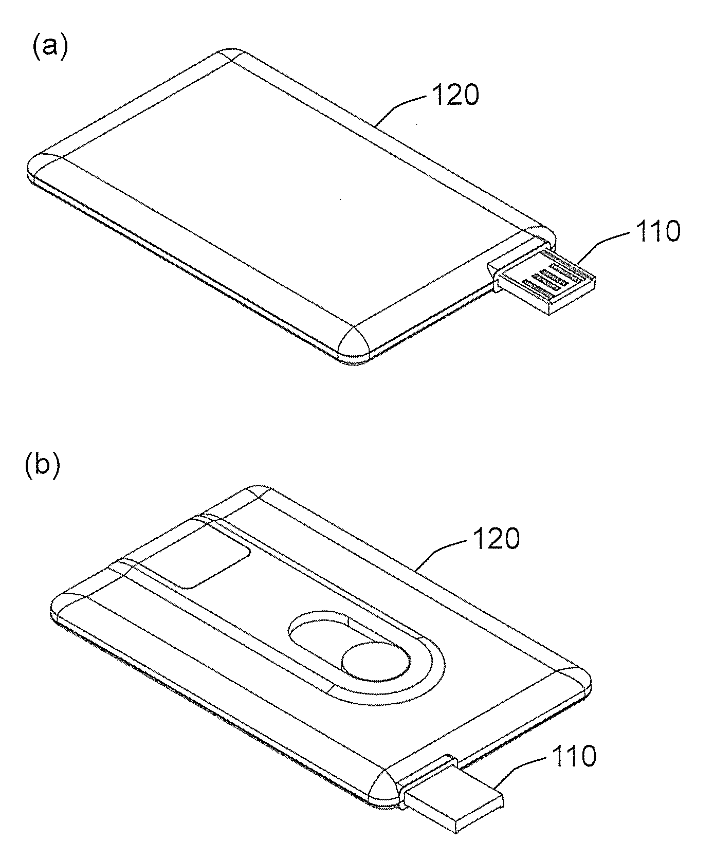
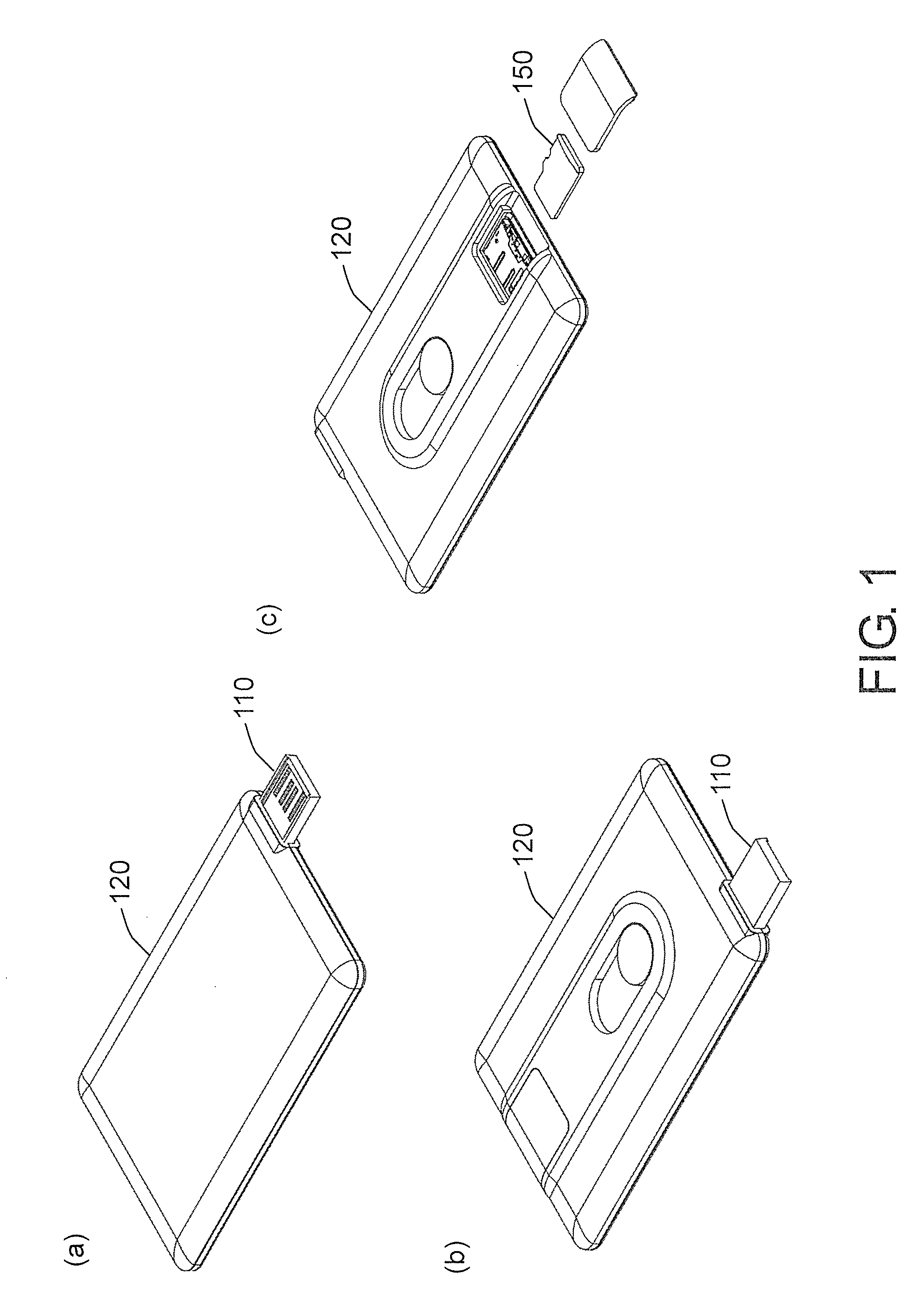
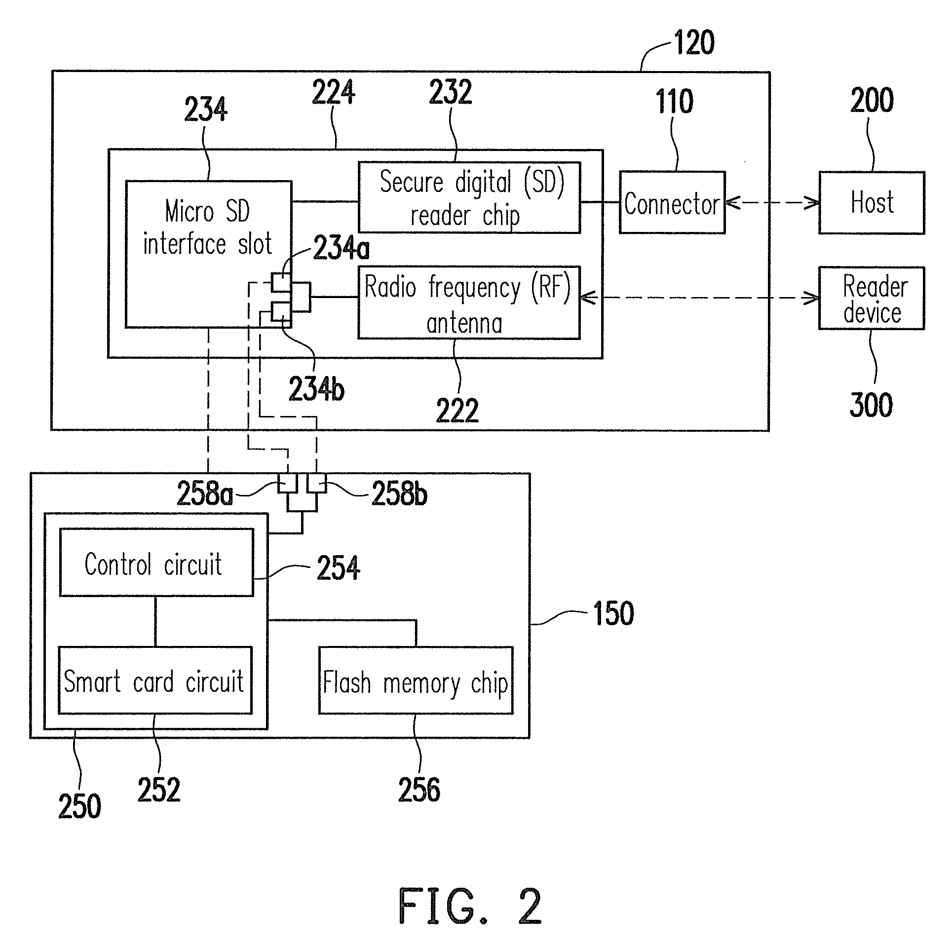
[0020]FIG. 1 is a diagram illustrating the appearance of a card reader according to an exemplary embodiment of the present invention, and FIG. 2 is a schematic block diagram of the card reader in FIG. 1.

[0021]Referring to both FIG. 1 and FIG. 2, the card reader includes a connector 110 and a carrier 120.

[0022]The connector 110 is used for connecting a host 200. In the present exemplary embodiment, the connector 110 is a universal serial bus (USB) connector. However, the present invention is not limited thereto, and in another exemplary embodiment of the present invention, the connector 110 may also be a PCI express connector, an IEEE 1394 connector, or other suitable connectors.

[0023]In the present exemplary embodiment, a radio frequency (RF) antenna 222 and a circuit board 224 are disposed in the carrier 120.

[0024]The RF antenna 222 receives and transmits RF signals to perform a near field communication (NFC) with a reader device 300 (for example, a RF reader). In the present exemp...

second exemplary embodiment

[0041]FIG. 4 is a diagram illustrating the appearance of a NFC device according to an exemplary embodiment of the present invention, and FIG. 5 is a schematic block diagram of the NFC device in FIG. 4.

[0042]Referring to both FIG. 4 and FIG. 5, the NFC device 400 includes a carrier 410 and a detachable micro SD memory card 420.

[0043]In the present exemplary embodiment, a RF antenna 512 and a micro SD interface slot 514 are disposed in the carrier 410.

[0044]The RF antenna 512 receives and transmits RF signals to perform a NFC with a reader device 300 (for example, a RF reader).

[0045]The micro SD interface slot 514 is used for connecting the micro SD memory card 420. To be specific, the micro SD memory card 420 is inserted into the micro SD interface slot 514 in a detachable manner. Particularly, in an exemplary embodiment of the present invention, the micro SD interface slot 514 is coupled to the RF antenna 512 through two RF pads 514a and 514b. Thus, the micro SD memory card 420 conn...


PUM


Abstract

A card reader with a near field communication (NFC) function is provided. The card reader includes a connector for connecting a host, a radio frequency (RF) antenna, and a circuit board having a secure digital (SD) reader chip and a micro SD interface slot. The micro SD interface slot has two RF pads coupled to the RF antenna, and a micro SD memory card having a flash memory chip, a control circuit, and a smart card circuit is inserted into the micro SD interface slot in a detachable manner. Thereby, the host can access data in the flash memory chip through the SD reader chip and the micro SD interface slot, and the smart card circuit can perform a NFC through the RF antenna and the micro SD interface slot.

Description

CROSS-REFERENCE TO RELATED APPLICATION[0001]This application claims the priority benefit of Taiwan application serial no. 98102039, filed on Jan. 20, 2009. The entirety of the above-mentioned patent application is hereby incorporated by reference herein and made a part of this specification.BACKGROUND OF THE INVENTION[0002]1. Field of the Invention[0003]The present invention relates to a card reader with a near field communication (NFC) function and a NFC device thereof, wherein a micro secure digital (SD) memory card having a smart card circuit can be connected to the card reader in a detachable manner.[0004]2. Description of Related Art[0005]Smart cards have been broadly used along with the widespread of e-wallet and prepayment applications. A smart card is an integrated circuit (IC) card embedded with such components as a microprocessor, a card operating system, a security module, and a memory and which allows a card holder to perform various predetermined operations. Besides the...

Claims


Application Information

Patent Timeline
Patent Type & Authority Applications(United States)
IPC IPC(8): G06K7/01
CPCG06K7/0004G06K19/07769G06K19/07732G06K7/10237
Inventor CHEN, CHANG-CHIHLO, JEN-WEI
Owner PHISON ELECTRONICS
Learn More