Relating to air-breathing flight vehicles

a technology for air intake and flight vehicles, applied in the field of flight vehicles and air intakes, can solve the problems of significant increase in complexity, mass and cost, instabilities in engine operation, and instability known as “buzz”, and achieve greater control over the effective geometry of the air intake compression surface and the shape of the shear layer

Inactive Publication Date: 2010-07-22
MBDA UK
View PDF18 Cites 20 Cited by
  • Summary
  • Abstract
  • Description
  • Claims
  • Application Information

AI Technical Summary

Benefits of technology

[0027]The outlet may comprise a plurality of apertures, which may be arranged to provide a plurality of independent jets of injected fluid, or one or more combined jet. Injection of the fluid from a plurality of apertures offers greater control over the shape of the shear layer that is formed; i.e. it offers greater control over the effective geometry of the air-intake compression surfaces.

Problems solved by technology

Actuating the surfaces can provide performance and operating benefits; however, there is significantly increased complexity, mass and cost, especially for axi-symmetric intake configurations.
Where multiple shocks are present and intersect, an interface vortex sheet can be formed at their intersection, which can cause an instability known as “buzz”.
Buzz is a cyclic interaction of the shock system and the flow within the intake, causing instabilities in the engine operation.
That approach to providing a variable-geometry air intake adds to the structural weight and complexity of the flight vehicle, which for many applications can severely reduce the net benefit from the variable geometry.
A shock wave intersecting with a surface can produce a very large pressure change in the boundary layer, causing it to separate from the rest of the flow.

Method used


Image

  • Relating to air-breathing flight vehicles
  • Relating to air-breathing flight vehicles
  • Relating to air-breathing flight vehicles

Examples


Embodiment Construction

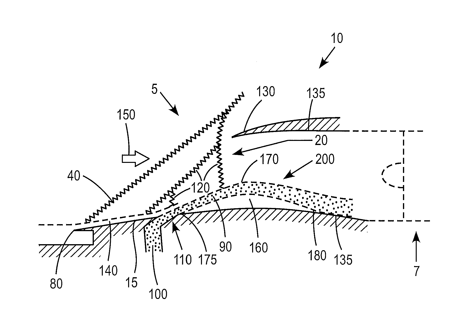
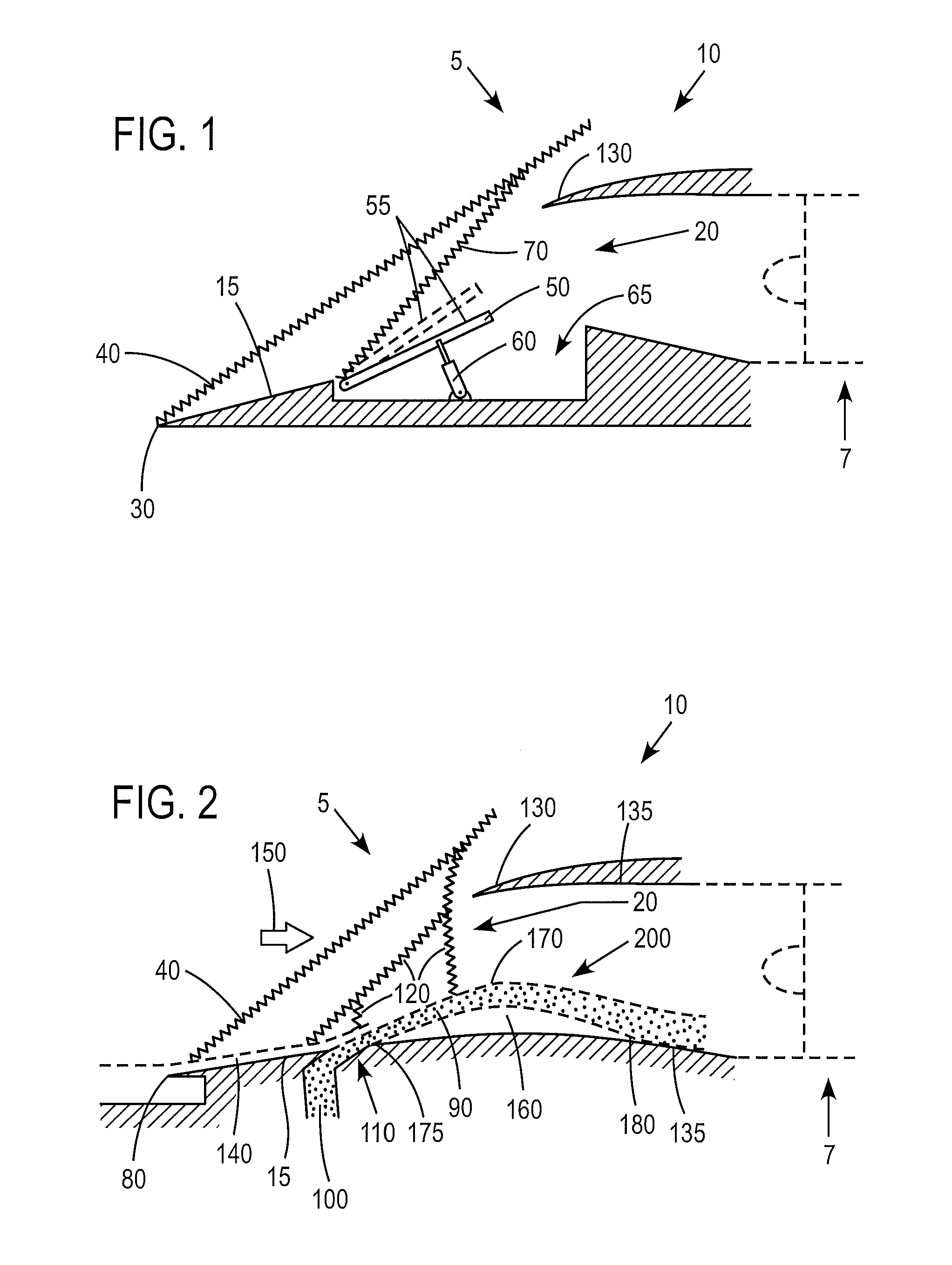
[0053]In example embodiments of the invention, an air intake for a supersonic air-breathing flight vehicle is equipped with a means for introducing or injecting air, in order to create predetermined regions of separated flow and an attendant fluid shear layer. The shear layer forms an aerodynamic boundary for the capture flow with a profile determined and optimised by appropriate injection of air so that the shock wave extends in an optimum orientation relative to a cowl lip of the intake thereby altering the effective shape of an air-intake. In this way, the air vehicle operation and performance is improved. The aerodynamic boundary so generated replaces mechanically moveable solid surfaces used to vary the geometry of prior-art intakes. Use of an introduced or injected air flow provides the advantages of a variable geometry, but with reduced weight and reduced mechanical complexity.

[0054]As mentioned in the discussion of the prior art herein above, known arrangements adopt a fuel ...


PUM


Abstract

An air intake for a supersonic air-breathing flight vehicle introduces or injects fluid in order to create predetermined regions of separated flow and an attendant fluid shear layer. This shear layer forms an aerodynamic boundary for the capture flow with a profile determined and optimised by appropriate injection of fluid. The aerodynamic boundary so generated replaces mechanically moveable solid surfaces used to vary the geometry of prior-art intakes. Use of an introduced or injected fluid can provide an advantage of a variable geometry, but with reduced weight and reduced mechanical complexity. In some embodiments, the injection of fluid has the effect of re-energising any ingested boundary layer, thus obviating the conventional requirement for a bleed system to provide boundary layer control.

Description

FIELD OF THE INVENTION[0001]This invention relates to controlling the effective shape of the compression surfaces of a supersonic engine intake to the field of air-breathing flight vehicles. The invention relates in particular to a flight vehicle having an air-breathing engine with a variable-geometry air intake. The invention relates especially, although not exclusively, to an air intake for an air-breathing engine for a supersonic flight vehicle.BACKGROUND ART[0002]Many flight vehicles, for example aircraft, obtain forward propulsion from air-breathing engines, i.e. jet engines. In the powerplant system of such an aircraft, air is taken in through a forward-facing air-intake and mixed with fuel, the mixture is ignited, and resultant exhaust gases are expelled, providing forward thrust. Optimisation of the geometric shape of the air intake according to flight condition and engine demand is known to provide performance benefits. Those benefits are particularly significant when fligh...

Claims


Application Information

Patent Timeline
Patent Type & Authority Applications(United States)
IPC IPC(8): B64D33/02B64C30/00
CPCF01D5/145F02C7/042F02C7/057Y02T50/673F02K7/10F02K7/16F02K1/30
Inventor RICHARDS, CLIFFORD JOHN
Owner MBDA UK
Why Eureka
Try Eureka