Sheet-conveying device and image-forming apparatus including the same

a technology of sheet conveyor and sheet conveyor, which is applied in the direction of electrographic process apparatus, thin material processing, instruments, etc., can solve the problems of insufficient cooling of sheets, insufficient hot airflow, and stacked sheets adhering to each other, so as to reduce and solve the problem of reducing the occurrence of jams

Active Publication Date: 2010-07-22
KYOCERA DOCUMENT SOLUTIONS INC
View PDF14 Cites 12 Cited by
  • Summary
  • Abstract
  • Description
  • Claims
  • Application Information

AI Technical Summary

Benefits of technology

[0010]It is an advantage of the present invention to provide a sheet-conveying device (post-fixation conveying device) and an image-forming apparatus including same wherein paper that has had an image fixed thereto is efficiently and uniformly cooled, and the occurrences of jams are reduced. Moreover, the reduction of these jams is easily solved.

Problems solved by technology

If the toner on the sheets was not sufficiently cooled, the stacked sheets may adhere to each other due to the stickiness of the toner.
Other potential issues may occur while the sheet is fed after fixation including feeding issues, such as jams.
This results in a hot airflow.
Since the sheet is fed in this hot airflow, the sheets may not be sufficiently cooled.
In the above technique, however, since the air is blown in the sheet width direction from the duct opening, there may be a difference in the cooling effect between an area near the duct opening and an area remote from the duct opening.
That is, the sheet may not be uniformly cooled.
Furthermore, blowing the air from one side in the sheet width direction and removing the air from the other side may cause the sheet to float.
Moreover, since the flow rate of the air varies with the position in the sheet width direction, air turbulence may occur.
This air turbulence tends to cause the sheet to float, resulting in jams in the sheet conveyance path.

Method used


Image

  • Sheet-conveying device and image-forming apparatus including the same
  • Sheet-conveying device and image-forming apparatus including the same
  • Sheet-conveying device and image-forming apparatus including the same

Examples


Embodiment Construction

[0024]Embodiments of the present invention will now be described with reference to the accompanying drawings. It should be noted that the present invention is not limited to the following embodiments. It should also be noted that applications of the present invention and terms and the like used herein are not limited to those described below.

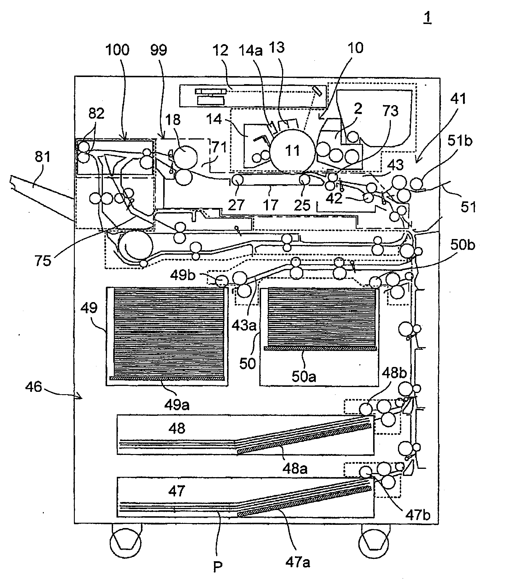
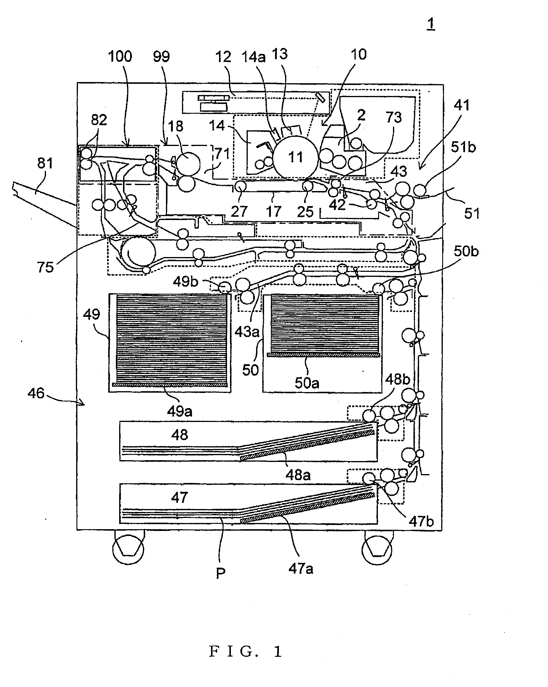
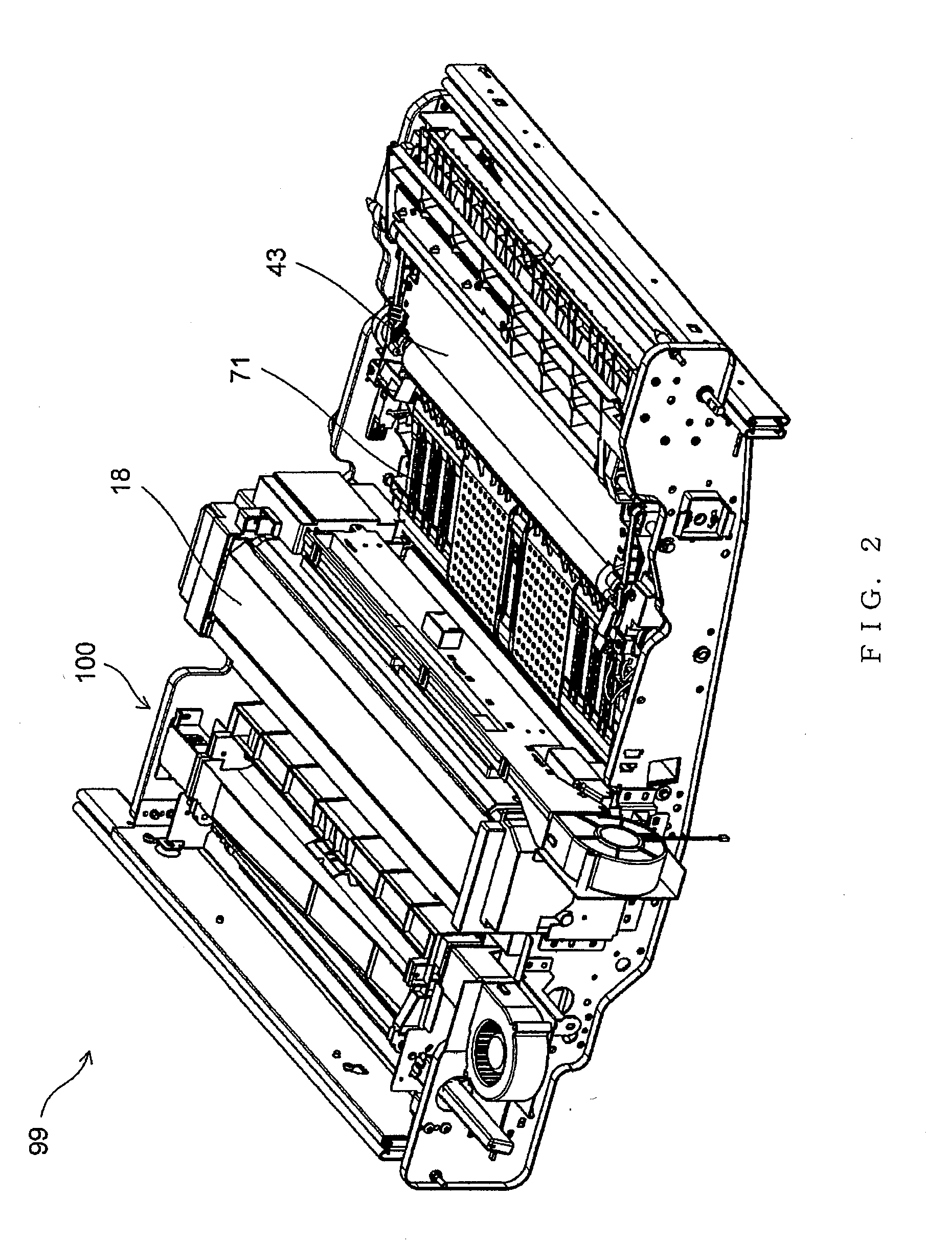
[0025]FIG. 1 is a schematic front view showing the internal design of an image-forming apparatus according to an embodiment of the present invention. The image-forming apparatus 1 has a rectangular housing and includes the following elements that are housed therein. An image-forming section 10 is provided in an upper part of the housing. The image-forming section 10 includes a photoreceptor 11, a developer 2, a charger 13, a cleaner 14, and a static eliminator 14a. The photoreceptor 11 is rotatable and has a photosensitive layer made of amorphous-silicon photosensitive material or organic photoconductor (OPC). The photoreceptor 11 is surrounded ...


PUM


Abstract

A sheet-conveying device designed to feed a sheet fed thereto through a fixing device toward a discharge unit includes first and second conveyance guides facing each other so as to define a sheet conveyance path and each having a conveying member designed to feed the sheet. The first conveyance guide includes a blower opening facing the sheet conveyance path for blowing air onto the sheet conveyance path, an exhaust opening provided on a downstream side in a sheet feeding direction with respect to the blower opening for removing air that has been blown onto the sheet conveyance path and discharging it outside the device.

Description

INCORPORATION BY REFERENCE[0001]This application is based upon and claims the benefit of priority from the corresponding Japanese Patent application No. 2009-011781l , filed Jan. 22, 2009, the entire contents of which are incorporated herein by reference.BACKGROUND[0002]1. Field of the Invention[0003]The present invention relates to sheet-conveying devices (post-fixation conveying devices) that are used in electrophotographic image-forming apparatuses such as copiers, printers, facsimiles, and multifunction machines having functions of the foregoing apparatuses, and to image-forming apparatuses including such sheet-conveying devices. In particular, the present invention relates to a sheet-conveying device (post-fixation conveying device) that cools sheets of paper that have had an image fixed thereto and to image-forming apparatuses including the sheet-conveying device.[0004]2. Description of the Related Art[0005]In general, fixation of an image to a sheet is performed at a high tem...

Claims


Application Information

Patent Timeline
Patent Type & Authority Applications(United States)
IPC IPC(8): B65H5/22B65H9/08
CPCG03G15/6573
Inventor SUMIKURA, NORIAKI
Owner KYOCERA DOCUMENT SOLUTIONS INC
Why Eureka
Try Eureka