

Phase shift control method for boost converter and circuit implementation
a phase shift control and converter technology, applied in the direction of dc-dc conversion, power conversion systems, ac networks with different sources at the same frequency, etc., can solve the problems of converters that cannot operate any more, the timing of the conduction state of the first and second driving signals has a fixed time lag, and the current of the phase inductor may fluctua
- Summary
- Abstract
- Description
- Claims
- Application Information
AI Technical Summary
Benefits of technology
Problems solved by technology
Method used
Image

Examples
Embodiment Construction
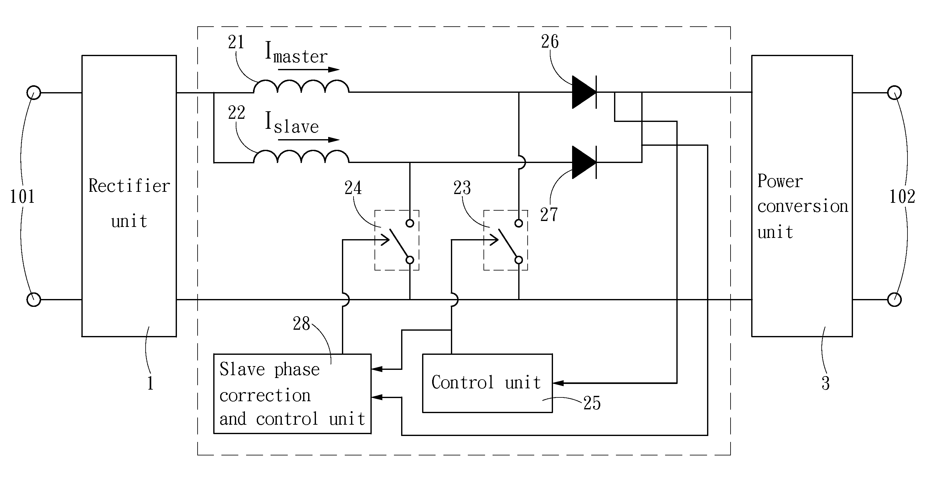
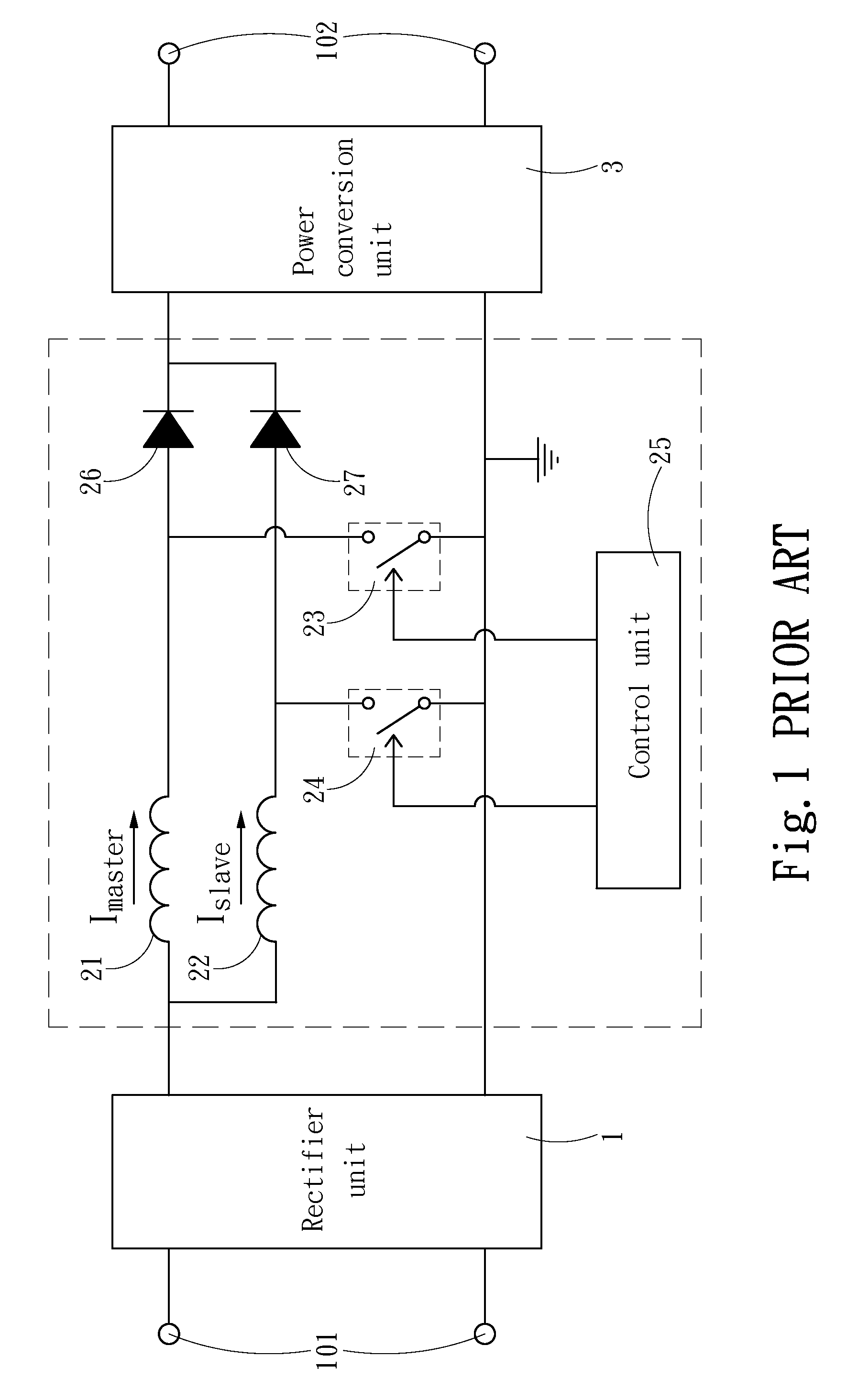
[0016]The present invention proposes a phase shift control method for a boost converter and circuit implementation. Refer to FIG. 5. The present invention applies to an interleaved paralleled boost converter (referred to as the boost converter 2 thereinafter) of a power supply. In the power supply, a rectifier unit 1 receives an input power via an input terminal 101 and rectifies the input power into a DC power. The booster converter 2 modulates the DC power into a modulated power and outputs the modulated power to a power conversion unit 3. The power conversion unit 3 converts the modulated power into the rated power and then outputs the rated power to the output terminal 102. The boost converter 2 comprises a master phase and at least one slave phase paralleled coupled to the master phase. The master phase has an inductor 21 and a diode 26 cascaded to the inductor 21; a first switch 23 is connected to between the inductor 21 and the diode 26. The slave phase has an inductor 22 and...
PUM
 Abstract
Description
Claims
Application Information