Coplanar waveguide fed planar log-periodic antenna

a logperiodic antenna and waveguide technology, applied in the direction of logperiodic antennas, resonant antennas, non-resonant long antennas, etc., can solve the problems of low radiation gain on the z-axis and energy loss inside the antenna, and achieve low cost, easy fabrication, and small volume

Active Publication Date: 2010-07-22
NAT TAIWAN UNIV
View PDF12 Cites 24 Cited by
  • Summary
  • Abstract
  • Description
  • Claims
  • Application Information

AI Technical Summary

Benefits of technology

[0016]Compared with the prior art, the CPW fed planar log-periodic antenna of the present invention not only has advantages of small volume, low cost, easy fabrication, but also encapsulates the planar log-periodic antenna through the wire structure and CPW-fed structure such that energy can only be transmitted in the encapsulated region without radiation, thereby decreasing cross polarized radiation of the antenna and enhancing the operating efficiency of the antenna.

Problems solved by technology

However, resonant current of such a structure generates energy in two orthogonal directions, i.e., cross-polarized radiation produced on an X-axis and a Y-axis, thereby resulting in energy loss inside the antenna and leading to low radiation gain on a Z-axis.

Method used


Image

  • Coplanar waveguide fed planar log-periodic antenna
  • Coplanar waveguide fed planar log-periodic antenna
  • Coplanar waveguide fed planar log-periodic antenna

Examples


Embodiment Construction

[0026]The following illustrative embodiments are provided to illustrate the disclosure of the present invention, these and other advantages and effects can be apparent to those skilled in the art after reading the disclosure of this specification.

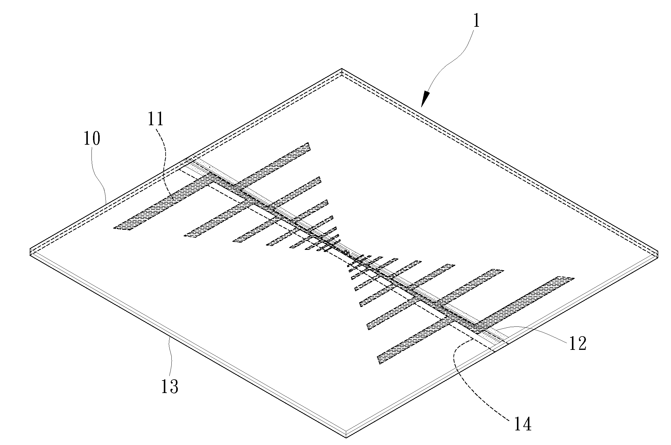
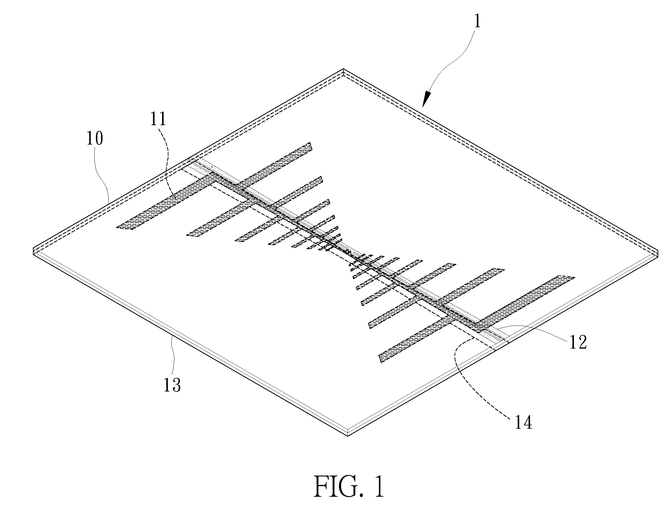
[0027]FIG. 1 is a perspective view of a CPW fed planar log-periodic antenna 1 according to the present invention. As shown in the drawing, the antenna comprises an upper substrate 10, a planar log-periodic antenna structure 11, a CPW-fed structure 12, a lower substrate 13 and a wire structure 14.

[0028]The upper substrate 10 and the lower substrate 13 can be a core substrate of a printed circuit board. The core substrate is generally composed of resin, reinforcement material and / or metal foil. The most common core substrate is a CCL (Copper Clad Laminate) substrate, which is formed by disposing a substrate under high temperature and high pressure and attaching a copper foil to a single surface or double surfaces of the substrate. A polymer r...


PUM


Abstract

A CPW fed planar log-periodic antenna is provided. The antenna includes: an upper substrate; a planar log-periodic antenna structure formed beneath the upper substrate; a CPW-fed structure formed on the upper substrate for feeding energy into the planar log-periodic antenna structure; a lower substrate disposed beneath the upper substrate; and a wire structure formed beneath the lower substrate. The antenna of the present invention features efficient reduction of cross polarized radiation and thereby enhancing the performance.

Description

BACKGROUND OF THE INVENTION[0001]1. Field of the Invention[0002]The present invention relates generally to an antenna structure, and more particularly to a planar log-periodic antenna using a coplanar waveguide (CPW)-fed technique.[0003]2. Description of Related Art[0004]As communication technology progresses and develops, communication products have become the most economical messaging devices that offer the most extensive range. While the communication products are getting increasingly relied on, more attention will be paid to its mobility and convenience. To overcome the drawbacks in wire communication networks such as inconvenient hardware architecture layout and limited application, wireless communication techniques have been accordingly born.[0005]Wireless communication products have been widely used in modern life as public communication devices or private portable devices. Therein, antennas play an important role in transmitting and receiving radio waves. An antenna is a cou...

Claims


Application Information

Patent Timeline
Patent Type & Authority Applications(United States)
IPC IPC(8): H01Q11/10
CPCH01Q11/105
Inventor LIN, YI-CHENG
Owner NAT TAIWAN UNIV
Why Eureka
Try Eureka