Controller driver, display device, and control method therefor

a display device and control method technology, applied in the field of controller drivers and display devices, can solve the problems of reducing transmissivity, increasing power consumption, increasing cpu processing load, etc., and achieves the effects of reducing cpu processing load and power consumption, reducing costs, and reducing transmissivity

Active Publication Date: 2010-07-22
RENESAS ELECTRONICS CORP
View PDF6 Cites 12 Cited by
  • Summary
  • Abstract
  • Description
  • Claims
  • Application Information

AI Technical Summary

Benefits of technology

[0009]The present inventor has found a problem that the input device disclosed by Ooya includes a liquid crystal panel stacked on a display device, which results in a reduction in transmissivity and an increase in costs.
[0010]Thus, there is a demand for reducing the CPU processing load and power consumption without causing a deterioration in display quality and an increase in costs.
[0011]A first exemplary aspect of the present invention is a controller driver that controls a display panel and a touch panel disposed on the display panel, the controller drier including: a display memory that stores image data to be displayed on the display panel; a touch panel control circuit that detects a touch panel signal from the touch panel; a cursor memory that stores cursor image data; and a composition circuit that combines the cursor image data stored in the cursor memory with the image data stored in the display memory based on the touch panel signal, to generate composite image data. With this configuration, the controller driver can output the image data, which is obtained by combining the image data stored in the display memory with the cursor image data, to the display panel. Thus, even when an external input is applied to the touch panel, it is not necessary for the CPU to generate composite image data. This results in a reduction in the CPU processing load. Moreover, power consumption associated with the transfer of image data from the CPU to the controller driver can be reduced.
[0012]A second exemplary aspect of the present invention is a control method for controlling a display panel and a touch panel disposed on the display panel, the control method including: storing image data to be displayed on the display panel into a display memory; detecting a touch panel signal from the touch panel; combining one of cursor image data and click image data with the image data stored in the display memory based on the touch panel signal, to generate composite image data; and outputting the composite image data to the display panel. With this control method, the controller driver can output the image data, which is obtained by combining the image data stored in the display memory with the cursor image data, to the display panel. Thus, even when an external input is applied to the touch panel, it is not necessary for the CPU to generate composite image data. This results in a reduction in the CPU processing load. Moreover, power consumption associated with the transfer of image data from the CPU to the controller driver can be reduced.
[0013]According to exemplary aspects of the present invention, it is possible to provide a controller driver and a display device that are capable of reducing the CPU processing load and power consumption.

Problems solved by technology

This causes problems such as an increase in CPU processing load and an increase in power consumption.
The present inventor has found a problem that the input device disclosed by Ooya includes a liquid crystal panel stacked on a display device, which results in a reduction in transmissivity and an increase in costs.

Method used


Image

  • Controller driver, display device, and control method therefor
  • Controller driver, display device, and control method therefor
  • Controller driver, display device, and control method therefor

Examples


first exemplary embodiment

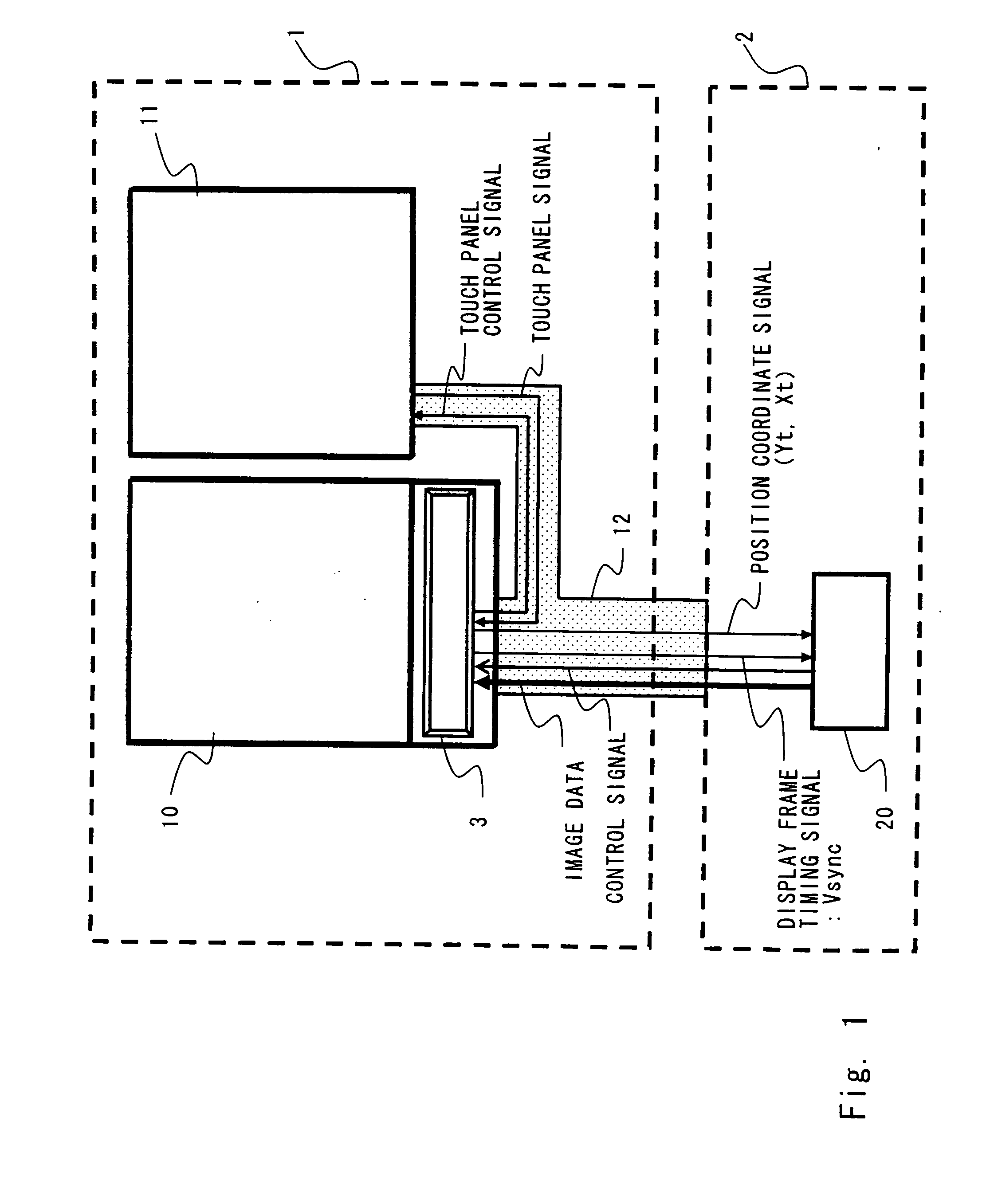
[0034]A controller driver and a display device according to a first exemplary embodiment of the present invention will be described with reference to FIGS. 1 to 6. A display device used for a cellular phone is herein described as an example of the display device. FIG. 1 is a diagram showing a schematic system configuration of a cellular phone according to this exemplary embodiment. As shown in FIG. 1, the cellular phone according to this exemplary embodiment includes a display block 1 and a cellular phone main-body block 2. The display block 1 includes a display panel 10 and a touch panel 11, and the cellular phone main-body block 2 includes a CPU 20.

[0035]Referring to FIG. 1, the touch panel 11 is disposed beside the display panel 10 for convenience of explanation, but the touch panel 11 is actually disposed on the display panel 10. Note that if the display panel 10 is an LCD, a backlight is separately provided in the display block, and the backlight, the display panel, and the tou...

second exemplary embodiment

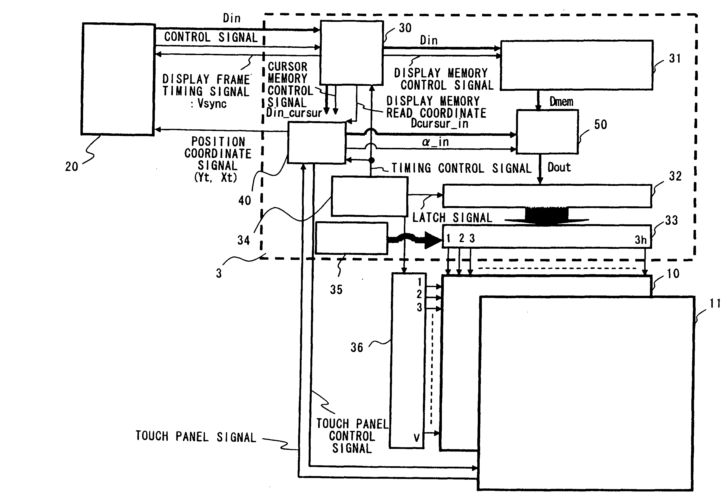
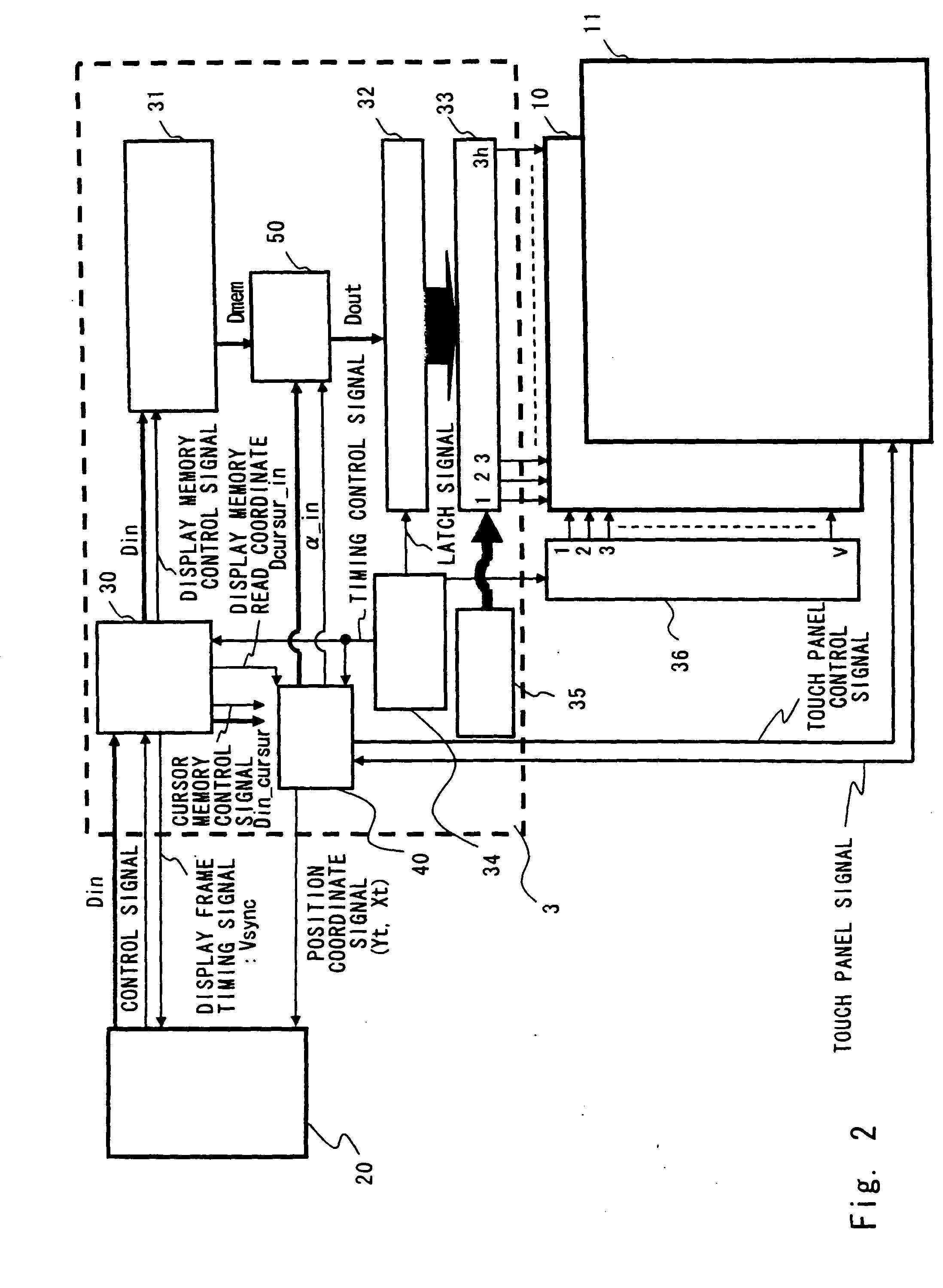
[0059]The configuration of the controller driver 3 according to a second exemplary embodiment of the present invention will be described with reference to FIGS. 7 to 12. The controller driver 3 according to this exemplary embodiment is used as the drive circuit of the display panel 10 including the touch panel 11, like in the first exemplary embodiment. FIG. 7 is a diagram showing the configuration of the controller driver 3 according to this exemplary embodiment. In FIGS. 7 to 12, components identical with those of FIGS. 1 to 6 are denoted by the same reference numerals, and the description thereof is omitted as appropriate.

[0060]As shown in FIG. 7, the controller driver 3 according to this exemplary embodiment includes the display memory 31, the latch circuit 32, the signal line drive circuit 33, the timing control circuit 34, the grayscale voltage generation circuit 35, the scanning line drive circuit 36, the touch panel control circuit 40, the composition processing circuit 50, ...


PUM


Abstract

A controller driver according to an exemplary embodiment of the present invention includes: a display memory that stores image data to be displayed on a display panel; a touch panel control circuit that detects a touch panel signal from the touch panel; a cursor memory that stores cursor image data; and a composition processing circuit that combines the cursor image data stored in the cursor memory with the image data stored in the display memory based on the touch panel signal, to generate composite image data.

Description

BACKGROUND[0001]1. Field of the Invention[0002]The present invention relates to a controller driver, a display device, and a control method therefor. In particular, the present invention relates to a controller driver incorporating a touch panel controller, a display device including a touch panel using the same, and a control method for the display device.[0003]2. Description of Related Art[0004]In recent years, products equipped with touch panels capable of inputting external information through a display screen have been developed in the field of mobile devices such as PDAs and cellular phones. FIG. 17 shows a schematic system configuration of a cellular phone according to a related art. As shown in FIG. 17, a display block 1 includes a display panel 10 and a touch panel 11, and a cellular phone main-body block 2 includes a CPU 20 and a touch panel controller 21. Note that if the display panel 10 is an LCD, a backlight is separately provided in the display block, and the backligh...

Claims


Application Information

Patent Timeline
Patent Type & Authority Applications(United States)
IPC IPC(8): G06F3/041G06F3/038
CPCG06F3/0416G09G5/08G09G5/377G06F3/04164
Inventor NOSE, TAKASHI
Owner RENESAS ELECTRONICS CORP
Why Eureka
Try Eureka