Projection optical system and method for photolithography and exposure apparatus and method using same

a technology of projection optical system and exposure apparatus, which is applied in the field of projection optical system, can solve the problems of increasing the reflection loss on the optical plane, slow production, and inability to ensure a large and effective numerical aperture on the image side, and achieves the effect of large and effective image-side numerical aperture, high efficiency, and inhibiting satisfactorily the reflection loss on the optical surfa

Inactive Publication Date: 2008-03-20
NIKON CORP
View PDF31 Cites 9 Cited by
  • Summary
  • Abstract
  • Description
  • Claims
  • Application Information

AI Technical Summary

Benefits of technology

[0026] An object of the invention is to provide a projection optical system which permits achievement of a large and effective image-side numerical aperture by providing a medium having a high refractive index in an optical path to the image field and inhibiting satisfactorily the reflection loss on the optical surface. Another object of the invention is to provide an exposure apparatus and an exposing method which have a large and effective image-side numerical aperture and enable to transfer and expose a fine pattern at a high accuracy via a projection optical system having a high resolution.
[0059] The projection optical system of the present invention may reduce the reflection loss on the optical surface, and finally ensure a large and effective image-side numerical aperture by imparting positive refraction power to the face of the boundary lens on the object side (first plane side). In the present invention, as described below, it is possible to achieve a projection optical system which enables to keep a large and effective image-side numerical aperture by inhibiting the reflection loss on the optical surface to a satisfactory level by providing a medium having a high refractive index in the optical path to the image field.
[0062] As described above, a fluorine-based inert liquid such as Florinat or a liquid such as deionized water is used as a medium having a high refractive index provided between the boundary lens between the boundary lens and the image field so as to make it possible to ensure a required transmissivity (to inhibit a light quantity loss). In the case of an exposure apparatus, the liquid may suffer from contamination by the photoresist coated onto a substrate such as a wafer. The contaminated liquid may stain the image-side optical surface of the boundary lens, causing a decrease in transmissivity of the boundary lens and the liquid.
[0068] In a reflection / refraction-type projection optical system having at least one concave reflector and a refractive optical system, in contrast, the concave reflector makes a contribution to the Petzval sum similar to that of a negative lens while having a positive refractive power. Correction of the Petzval sum can be easily made through a combination of the concave reflector and the positive lens. As a result, it is possible to achieve a projection optical system having a large image-side numerical aperture and a wide effective image forming area (effective exposure area) by a combination of a configuration of the reflection / refraction optical system and a configuration of a liquid-immersion optical system in which a liquid (medium) having a high refractive index is provided in the optical path from the image plane.
[0069] In the reflection / refraction optical system, a problem is how to separate a beam directed toward the concave reflector from a return beam reflected from the concave reflector. In a projection optical system having a large image-side numerical aperture, increase in the effective diameter of the optical element (adoption of larger optical elements) is inevitable. Therefore, in a reflection / refraction optical system using a prism-type beam splitter having a transmission reflection surface, the difficulty is encountered that it is difficult to manufacture a larger-sized prism-type beam splitter. The projection optical system should preferably have a configuration in which the system has an effective image forming area eccentric from the optical axis, and at least one intermediate image is formed in the optical path. In this configuration, it is possible to easily separate the beam directed toward the concave reflector from the return beam reflected from the concave reflector by arranging a flat reflector for separating the optical paths near the forming position of the intermediate image.
[0070] Furthermore, the configuration should preferably be such that the projection optical system comprises a first image forming optical system which forms a first intermediate image of the object surface (the first plane); a second image forming optical system which has at lease one concave reflector and forms a second intermediate image on the basis of the flux from the first intermediate image; and a third image forming optical system which forms a final image on an image field (the second plane) on the basis of the flux from the second intermediate image; a first deflection mirror is arranged in an optical path between the first image forming optical system and the second image forming optical system; a second deflection mirror is arranged in an optical path between the second image forming optical system and the third image forming optical system; and the optical axis of the first image forming optical system agrees with the optical axis of the third image forming optical system. In this configuration, even in an optical system having a large image-side numerical aperture, it is possible to easily separate the beam directed toward the concave reflector from the beam reflected by the concave reflector to return. It is also possible to relatively easily accomplish assembly or adjustment of optical systems since the first image forming optical system and the third image forming optical system are coaxial.

Problems solved by technology

When it is tried to increase the numerical aperture by adopting a larger medium incident angle θ, the incident angle on the image plane and the outgoing angle from the projection optical system become larger, leading to an increase in reflection loss on the optical plane.
It is impossible to ensure a large and effective numerical aperture on the image side.
However, a concrete proposal has not as yet been made regarding a configuration which ensures a large and effective image-side numerical aperture.
Liquid immersion applied to microlithography has also been proposed for many years, but has been slow to be adopted in production, no doubt because of practical difficulties.
However, neither of these papers addresses the issues of optical design.
However, this is a small-field system (<1 mm), specifically intended for optical inspection, and there is no indication that the design could be applied to the much larger field sizes and extremely small residual aberrations and distortion required for microlithography.
A reduction in field size and an increase in reduction ratio above 4× would help these issues, but would make the “wet” lithography tools incompatible with current “dry” systems.
However, they cannot be converted to liquid immersion only by adding a liquid to the space between the last element and the wafer.
This would introduce a large amount of spherical aberration, which has to be compensated elsewhere in the design.
It is therefore not obvious to one skilled in the art of optical design that the NA of a “dry” projection lens can be increased in the ratio of the refractive index of the immersion liquid, without both an impractical increase in the lens size and complexity, as well as an unacceptable increase in residual aberrations.

Method used


Image

  • Projection optical system and method for photolithography and exposure apparatus and method using same
  • Projection optical system and method for photolithography and exposure apparatus and method using same
  • Projection optical system and method for photolithography and exposure apparatus and method using same

Examples


fourth embodiment

[0145] The exposure apparatus of this embodiment has a configuration in which, from among the optical members forming the projection optical system PL, the interior of the projection optical system PL is kept in an air-tight state between the optical member arranged at a position the closest to the reticle (in the fourth embodiment, the lens L11) and the boundary lens Lb arranged at a position the closest to the wafer W. The gas in the projection optical system PL is substituted by an inert gas such as helium gas or nitrogen or kept substantially in a vacuum state. The reticle R, the reticle stage RS and the like are arranged in a narrow optical path between the illuminating optical system IL and the projection optical system PL. The inert gas such as nitrogen or helium gas is filled in the interior of a casing (not shown) hermetically enclosing the reticle R, the reticle stage RS and the like, or the interior is maintained substantially in a vacuum state.

[0146]FIG. 10 schematically...

second embodiment

[0156] In the second embodiment, an ArF excimer laser source is used as a light source 100. Quartz (SiO2) is used for all the refracting optical members (lens components) forming the projection optical system PL and the parallel flat sheet Lp. The ArF excimer laser beam which is the exposure light has an oscillation center wavelength of 193.306 nm, and quartz has a refractive index of 1.5603261 for this center wavelength. Deionized water having a refractive index of 1.47 for the exposure light is used as the medium Lm present between the boundary lens Lb and the wafer W.

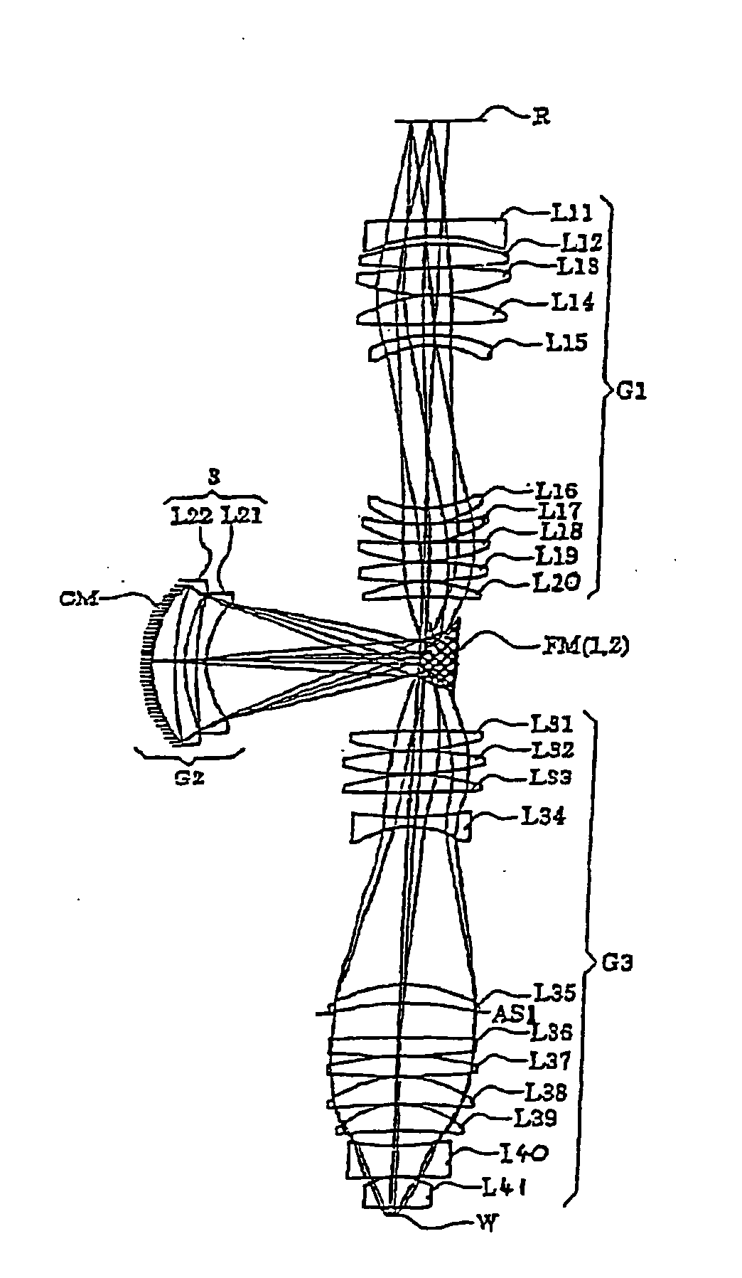
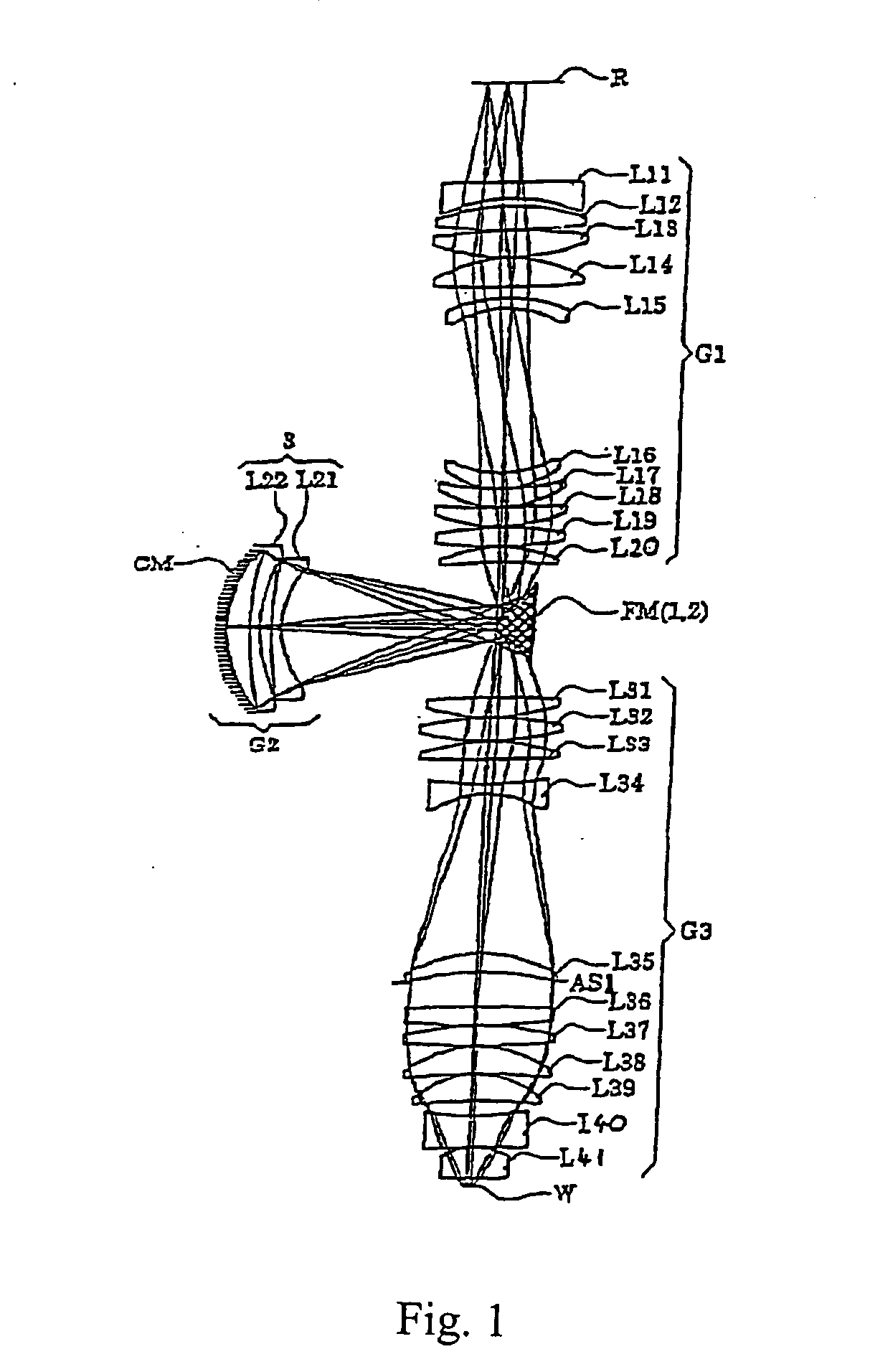
[0157] In the projection optical system PL in the second embodiment, the first image forming optical system G1 comprises, sequentially from the reticles side, a positive meniscus lens L11 with a convex face thereof directed toward the reticle; a biconvex lens L12 with an aspherical convex surface or face thereof directed toward the wafer; a positive meniscus lens L13 with a convex surface thereof directed toward the ...

third embodiment

[0169] In the projection optical system PL of the third embodiment, the first image forming optical system G1 comprises, sequentially from the reticle side, a positive meniscus lens L11 with a convex surface thereof directed toward the reticle; a biconvex lens L12 with an aspherical convex surface thereof directed toward the wafer; a positive meniscus lens L13 with a convex surface thereof directed toward the reticle; a positive meniscus lens L14 with a concave surface thereof directed toward the reticle; a negative meniscus lens 115 with a concave surface thereof directed toward the reticle; a negative meniscus lens L16 with a concave surface thereof directed toward the reticle; a positive meniscus lens L17 with an aspherical concave surface thereof directed toward the reticle; a positive meniscus lend L18 with a concave surface thereof directed toward the reticle; a biconvex lens L19; and a biconvex lens L110 with an aspherical surface thereof directed toward the wafer.

[0170] The ...


PUM

PropertyMeasurementUnit
field sizesaaaaaaaaaa
refractive indexaaaaaaaaaa

Abstract

A projection lens of a microlithographic projection exposure apparatus includes a final lens element and a terminating element having no overall refractive power that is positioned between, but spaced apart from, the final lens element and an image plane of the projection lens. The image plane is adjustably positioned such that a position of the image plane with respect to the final lens element is adjustable.

Description

[0001] This is a Continuation of application Ser. No. 10 / 525,372, which is the U.S. National Stage of International Application No. PCT / JP2003 / 010665 filed Aug. 22, 2003. The disclosure of each of the prior applications is hereby incorporated by reference herein in its entirety.TECHNICAL FIELD [0002] The present invention relates to projection optical systems such as systems for photolithography. [0003] The present invention also relates to an exposure apparatus and exposing methods. The invention is applicable to a high-resolution projection optical system suitable for an exposure apparatus used when manufacturing semiconductor elements or liquid crystal display elements through a photolithographic process. BACKGROUND ART [0004] In the following the term “anastigmat” means an optical element or group of optical elements adapted to reduce astigmatism and / or aberrations including spherical aberration. See, e.g. Naumann / Schröder, Bauelemente der Optik, Carl Hauser Verlag München Wien,...

Claims


Application Information

Patent Timeline
Patent Type & Authority Applications(United States)
IPC IPC(8): G03B27/54G02B3/00G02B13/14G02B13/18G02B13/24G02B17/08G03F7/20H01L21/027
CPCG02B13/22G02B17/08G03F7/70341G02B21/33G03F7/70225G02B17/0892G03F7/20
Inventor OMURA, YASUHIROIKEZAWA, HIRONORI
Owner NIKON CORP
Why Eureka
Try Eureka