Active cooling of crystal optics for increased laser lifetime

a technology of active cooling and crystal optics, applied in the field of cooling systems, can solve the problems of lowering the overall cost of laser operation and ownership, and achieve the effects of reducing the operating temperature of beam-conveying optics, reducing optic degradation, and reducing operating temperatur

Inactive Publication Date: 2008-08-21
CORNING INC
View PDF2 Cites 19 Cited by
  • Summary
  • Abstract
  • Description
  • Claims
  • Application Information

AI Technical Summary

Benefits of technology

[0007]The invention is based partly on a discovery that reducing the operating temperatures of beam-conveying optics can significantly reduce degradation in the optics associated with the transmission of high concentrations of light energy. In particular, fluoride crystal materials such as calcium fluoride have been found to benefit from the reduction in operating temperature. Retarding transmission losses in the beam-conveying optics extends the service lives of high-power lasers, which reduces production downtime and lowers the overall cost of laser operation and ownership.
[0008]Actively cooling the fluoride crystal optics reduces the rate at which transmission declines with accumulating fluence (e.g., numbers of laser pulses). Although the exact mechanism by which the reduction in temperature reduces the rate of transmission decline is not clearly understood, the slower atomic motion associated with the lower temperatures is believed to reduce the mobility of fluorine ions and improve their chances of recombining with their cations within the crystal lattice after being temporarily disassociated by interactions with high energy photons. Reductions in transmissivity are associated with increased absorption and a corresponding increase in temperature. By both delaying the onset of significant absorption and reducing the subsequent temperature increases associated with absorption, active cooling is believed to contribute to the slower degradation in the fluoride crystal optics.
[0009]One version of the invention as a laser system includes a laser for generating the laser beam and an enclosed pathway within which the laser beam is conveyed. The laser has a predetermined operating temperature. A crystal optic, which has a service life associated with a threshold reduction in transmissivity, transmits the laser beam within the enclosed pathway at a predetermined concentration of light energy. An active cooling system in thermal contact with the crystal optic lowers a nominal temperature of the crystal optic below the operating temperature of the laser to extend the service life of the crystal optic or accommodate a higher concentration of light energy without correspondingly shortening the service life.
[0016]Another version of the invention improves a crystal optical component for transmitting light at concentrations that progressively degrade the transmissivity of the component. A crystal body of the optical component has a light transmitting region surrounding an optical axis. An active cooling system extracts heat from the crystal body for reducing a rate at which the crystal body degrades in transmissivity or for accommodating higher concentrations of light without correspondingly increasing the progressive degradation in transmissivity. The active cooling system is arranged in thermal contact with multiple portions of a periphery of the crystal body to extract heat symmetrically with respect to the optical axis.
[0019]The invention can also be practiced as a method of extending service lives of crystal optics that transmit concentrated laser beams. The laser beam is generated by a laser and is transmitted within an enclosed pathway through at least one crystal optic at a power density that progressively degrades transmissivity of the crystal optic with accumulating fluence. The crystal optic is actively cooled to slow the progressive degradation in the transmissivity of the crystal optic with the accumulating fluence or to accommodate a higher power density without correspondingly increasing the progressive degradation in transmissivity.

Problems solved by technology

Retarding transmission losses in the beam-conveying optics extends the service lives of high-power lasers, which reduces production downtime and lowers the overall cost of laser operation and ownership.

Method used


Image

  • Active cooling of crystal optics for increased laser lifetime
  • Active cooling of crystal optics for increased laser lifetime
  • Active cooling of crystal optics for increased laser lifetime

Examples


Embodiment Construction

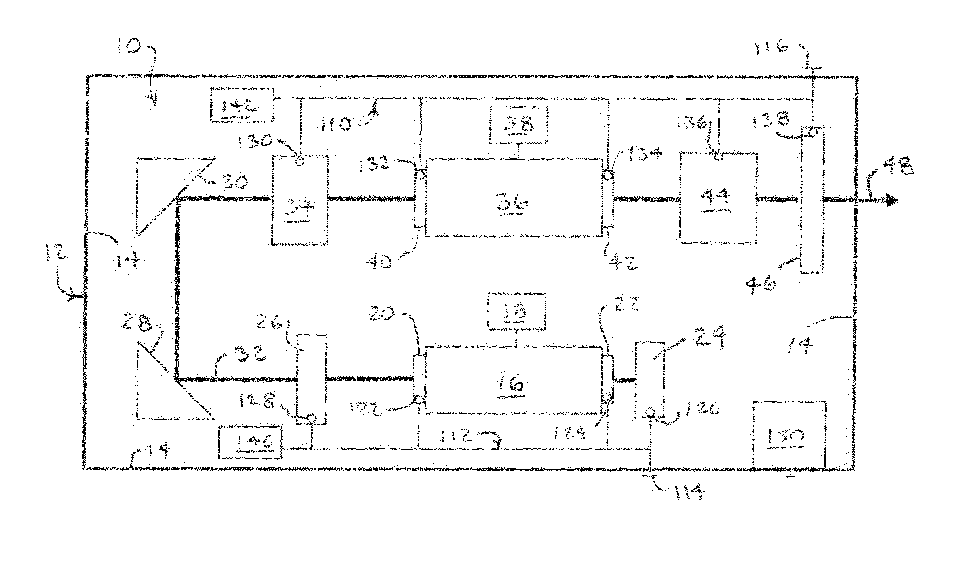
[0030]A laser generating apparatus 10 as depicted in FIG. 1 is mounted within a housing 12 providing an enclosed pathway for isolating the laser generating apparatus from a surrounding environment. The housing 12 is preferably filled with an inert gas, such as nitrogen N2. The walls 14 of the housing 12 can also be arranged to insulate the contents of the housing 12 from changes in ambient temperature.

[0031]The laser generating apparatus 10 includes a gas-filled oscillator 16 powered by a control module 18. A gain medium is confined within the oscillator 16 by windows20 and 22. A resonant cavity is formed through the oscillator between a line-narrowing module 24 and an output coupler 26. Mirrors 28 and 30 convey a developing laser beam 32 to a beam shaper and aligner 34 in advance of an amplifier 36. A control module 38 powers the amplifier 36 to augment and stabilize pulse energy. The amplifier 36 can be arranged as a similar discharge chamber with windows 40 and 42 arranged for co...


PUM


Abstract

A laser beam is generated and transmitted within an enclosed pathway through at least one crystal optic at a power density that progressively degrades transmissivity of the crystal optic with accumulating fluence. The crystal optics are cooled below normal operating temperatures to slow the progressive degradation in the transmissivity of the crystal optics with the accumulating fluence or to accommodate a higher power density without correspondingly increasing the progressive degradation in transmissivity.

Description

TECHNICAL FIELD[0001]The invention relates to cooling systems for reducing the operating temperatures of optical elements, particularly optical elements intended for transmitting high concentrations of light energy within housings or other enclosed pathways.BACKGROUND OF THE INVENTION[0002]Lasers arranged for light intensive activities, such as photolithography, can be expensive to operate and maintain. Part of this cost relates to stringent requirements for conditioning laser beams and another part of this cost relates to the limited service lives of such lasers between required refurbishing. The beam-conveying optics, which are often located in an isolated environment within a laser housing or other enclosed pathway, participate in such activities as beam amplification, beam shaping, wavelength selection, and bandwidth control. High-power lasers, such as Excimer lasers and frequency-doubled solid-state lasers, generate high concentrations of light energy that can progressively dam...

Claims


Application Information

Patent Timeline
Patent Type & Authority Applications(United States)
IPC IPC(8): H01S3/04
CPCG03F7/70025H01S3/0014H01S3/005H01S3/2366H01S3/0401H01S3/2308H01S3/02
Inventor CLAR, COLLEEN RENEEROSCH, WILLIAM ROGERSSCHREIBER, HORSTSMITH, CHARLENE MARIE
Owner CORNING INC
Why Eureka
Try Eureka