Aerodynamic Measurement Probe of an Airstream Along a Wall

Active Publication Date: 2010-07-29
THALES SA
View PDF10 Cites 9 Cited by
  • Summary
  • Abstract
  • Description
  • Claims
  • Application Information

AI Technical Summary

Benefits of technology

[0015]It is therefore a subject of the present invention to remedy these defects by proposing a s

Problems solved by technology

It has already been seen that the travel time measurement

Method used


Image

  • Aerodynamic Measurement Probe of an Airstream Along a Wall
  • Aerodynamic Measurement Probe of an Airstream Along a Wall
  • Aerodynamic Measurement Probe of an Airstream Along a Wall

Examples


Example

[0022]In the interests of clarity, the same elements are given the same references in the different figures.

DETAILED DESCRIPTION OF THE PREFERRED EMBODIMENT

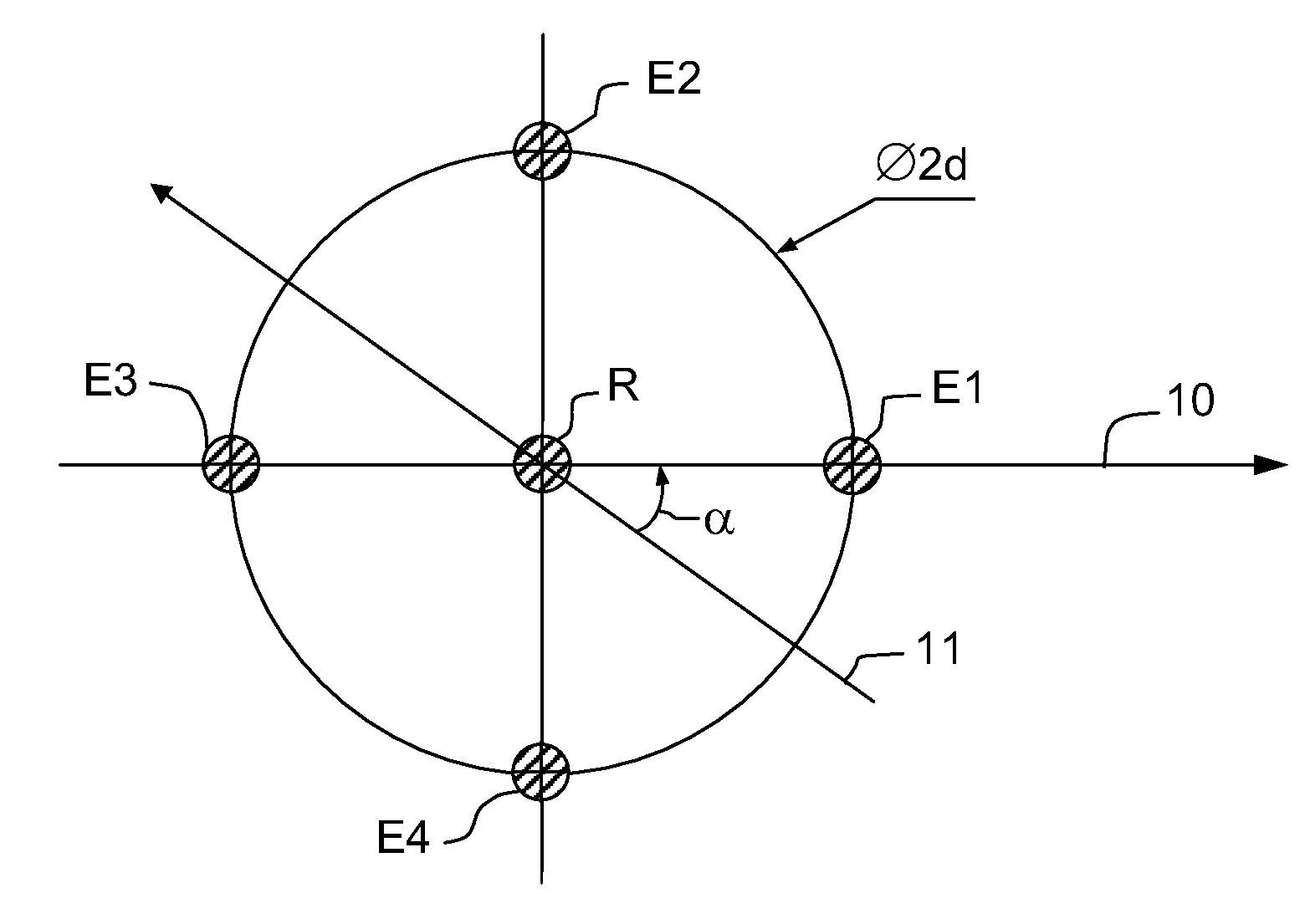
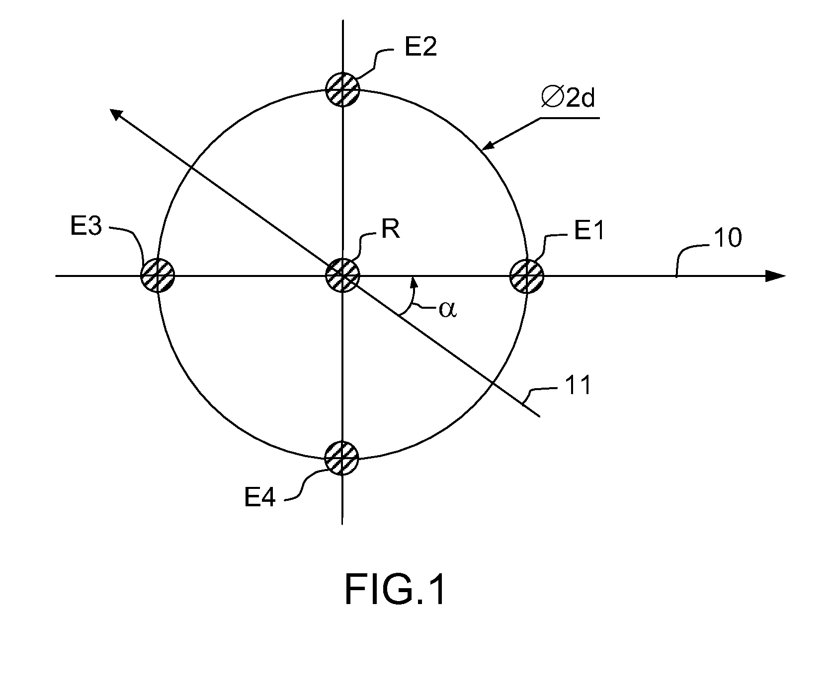
[0023]FIG. 1 represents a device according to the invention and comprising four emitters E1, E2, E3, E4, that are identical for example, and a single receiver R. It is, of course, possible to implement the invention based on two emitters that can emit a sound wave received by the single receiver R. The sound wave can be ultrasound, for example at a frequency of the order of 40 kHz. The receiver R can be a microphone sensitive to the waves emitted by the emitters or resonant, that is to say sensitive to a particular frequency.

[0024]The emitters E1, E2, E3 and E4 are all substantially coplanar in a plane tangential to the surface of a wall, for example the skin of an airplane. The plane tangential to the surface of the skin is that of FIG. 1. The emitters E1, E2, E3 and E4 are advantageously distributed around the receiver R. They ...


PUM


Abstract

The invention relates to an aerodynamic measurement probe of an airstream along a wall. The invention makes it possible notably to determine the attack of an airstream relative to an axial reference tangential to the wall. The invention is particularly useful in the aeronautical field. According to the invention, the probe comprises several emitters that can each emit a sound wave and a receiver sensitive to the different sound waves. Thus, there is forewarning of the receiver error that is common to all the measurements of travel time of a sound wave between one of the emitters and the receiver.

Description

CROSS-REFERENCE TO RELATED APPLICATIONS[0001]This application claims priority of foreign French patent application no. FR 0807392, filed Dec. 23, 2008, the disclosure of which is hereby incorporated by reference in its entirety.BACKGROUND OF THE INVENTION[0002]The invention relates to an aerodynamic measurement probe of an airstream along a wall. The invention makes it possible notably to determine the attack of an airstream relative to an axial reference tangential to the wall. The invention is particularly useful in the aeronautical field where knowledge of the attack of an airstream surrounding an aircraft is essential to the piloting of the aircraft. The attack relative to a horizontal plane is an important parameter for determining the buoyancy of the aircraft for example in a landing. The attack relative to a vertical plane is also important representing the side slip of the aircraft. To determine these two parameters, attack and side slip, it is possible to locally measure th...

Claims


Application Information

Patent Timeline
IPC IPC(8): G01P5/00
CPCG01P5/245G01P13/02
Inventor CHOISNET, JOEL
Owner THALES SA
Why Eureka
Try Eureka