Engine control apparatus

Inactive Publication Date: 2010-07-29
KOMATSU LTD
View PDF29 Cites 27 Cited by
  • Summary
  • Abstract
  • Description
  • Claims
  • Application Information

AI Technical Summary

Benefits of technology

[0030]In an engine control apparatus according to an embodiment of the invention, a first target speed of an engine is set by a first target speed set means with an engine speed set dial, a second target speed calculation means calculates a second target speed controlling the maximum target speed of the engine according

Problems solved by technology

As illustrated in FIG. 10, the regulation line Fe corresponds to a region where the fuel efficiency is relatively large on the iso fuel efficiency curve M. Thus, according to a conven

Method used


Image

  • Engine control apparatus
  • Engine control apparatus
  • Engine control apparatus

Examples


Example

EXPLANATIONS OF LETTERS OR NUMERALS

[0041]1: CONSTRUCTION MACHINE

[0042]2: ENGINE

[0043]3: HYDRAULIC PUMP

[0044]4: ENGINE CONTROLLER

[0045]5: PUMP CONTROL VALVE

[0046]6: CONTROLLER

[0047]7-9: HYDRAULIC SENSOR

[0048]10: PTO SHAFT

[0049]11: GENERATOR MOTOR

[0050]12: STORAGE BATTERY

[0051]31-36: HYDRAULIC ACTUATOR

[0052]41, 42: OPERATION LEVER

[0053]43, 44: TRAVEL LEVER

[0054]51: ENGINE SPEED SET UNIT

[0055]52: ENGINE MAXIMUM SPEED CALCULATION UNIT IN RELIEF OPERATION

[0056]53: MINIMUM SELECTION UNIT

BEST MODE(S) FOR CARRYING OUT THE INVENTION

[0057]Hereinafter, an engine control apparatus according to an embodiment of the invention will now be described with reference to the accompanying drawings. In the embodiment, cases of controlling a diesel engine and a hydraulic pump installed on a construction machine such as a hydraulic shovel will be described.

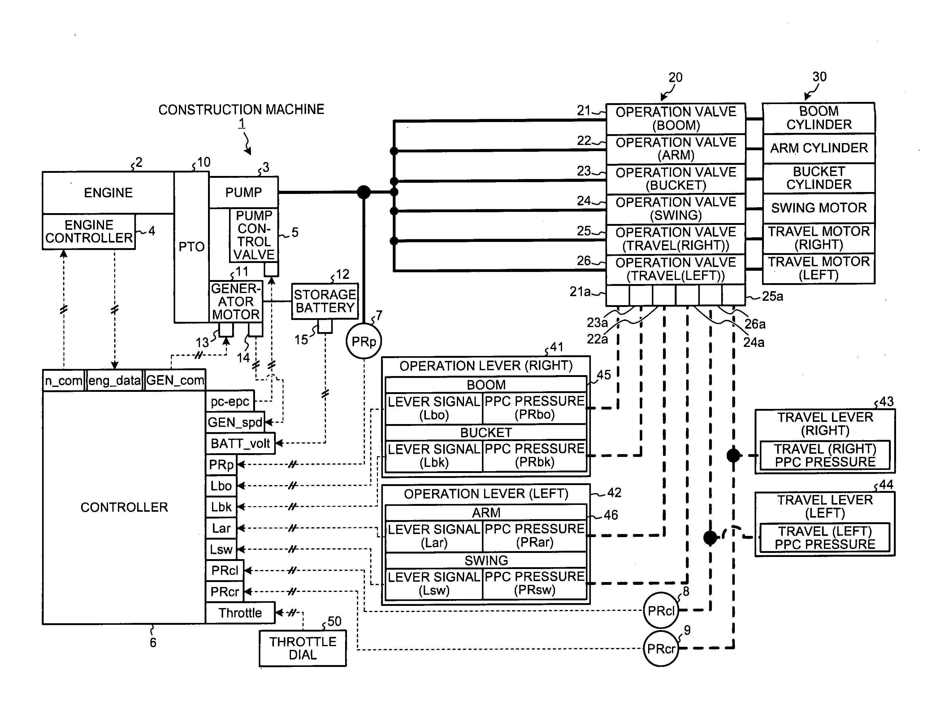
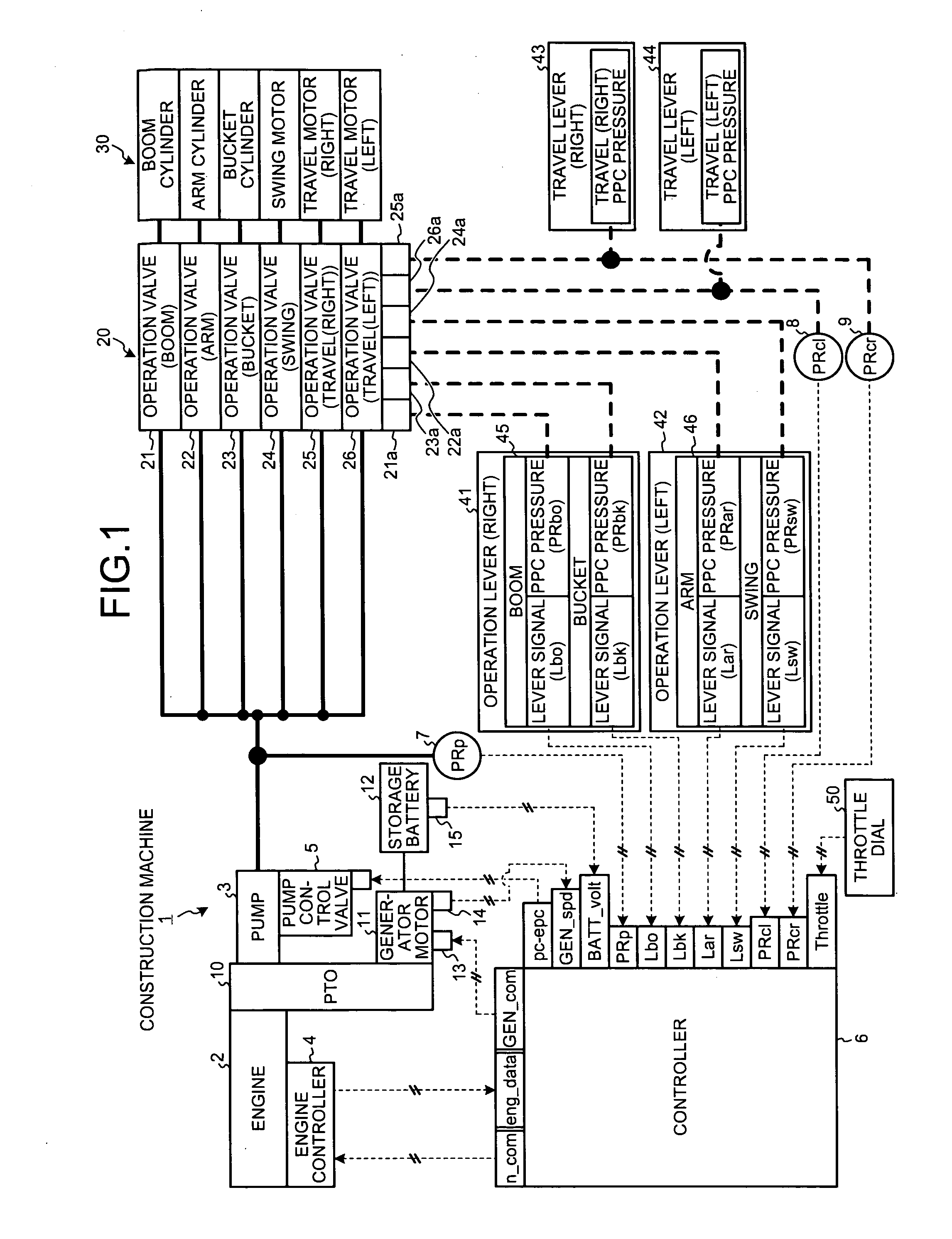
[0058]FIG. 1 is a schematic view illustrating an entire structure of a construction machine 1 according to an embodiment of the invention. The construct...


PUM


Abstract

An engine control apparatus includes an engine target speed set unit 51 setting a first target speed through a throttle dial, a relief engine maximum speed calculation unit 52 calculating a second target speed limiting a maximum target speed in a relief operation according to a load pressure of a hydraulic pump, a speed control means controlling an engine speed such that the engine speed is equal to lower one of the first target speed and the second target speed, a determination means determining whether an engine torque assist action of a generator motor is performed, based on a deviation between an target speed and a real speed of the engine. When the determination means determines that the engine torque assist action is performed, the speed control means controls the engine speed to be equal to the target speed through the engine torque assist action of the generator motor.

Description

TECHNICAL FIELD[0001]The present invention relates to an engine control apparatus configured to drive a hydraulic pump through an engine.BACKGROUND ART[0002]In the related art, diesel engines are installed on construction machines including hydraulic shovels, bulldozers, dump trucks, and wheel loaders.[0003]FIG. 9 illustrates a configuration of a conventional construction machine 100. Referring to FIG. 9, the construction machine 100 uses an engine 2, which is a diesel engine, as a driving source to drive a hydraulic pump 3. A capacity variable type hydraulic pump is used as the hydraulic pump 3, and a tilt angle of an inclined plate 3a of the hydraulic pump 3 is varied to change a capacity q (cc / rev). Pressure oil discharged at a discharge pressure PRP and a flow rate Q (cc / min) from the hydraulic pump 3 are supplied to hydraulic actuators 31, 32, 33, 34, 35, and 36 including a boom cylinder 31 through operation valves 21, 22, 23, 24, 25, and 26. The operation valves 21, 22, 23, 24...

Claims


Application Information

Patent Timeline
IPC IPC(8): F02D41/00
CPCB60L2240/421B60L2200/26B60L2240/486B60W10/06B60W10/08B60W20/00B60W2510/0604B60W2510/244B60W2540/16B60W2710/0605B60W2710/0644B60W2710/081B60W2710/083B60Y2200/14E02F9/2246F02D29/04F02D29/06F02D31/001F02D31/006F02D41/0205F02D41/021F02D2250/24F04B17/05F04B49/065F04B2205/05Y02T10/6286Y02T10/642E02F9/2075B60W10/04B60W20/40B60L2240/423Y02T10/64Y02T10/62B60K2006/268
Inventor KAWAGUCHI, TADASHIMORINAGA, JUNINOUE, HIROAKI
Owner KOMATSU LTD
Why Eureka
Try Eureka