
Circuit board structure and fabrication method thereof

Active Publication Date: 2010-07-29
UNIMICRON TECH CORP
View PDF5 Cites 11 Cited by
  • Summary
  • Abstract
  • Description
  • Claims
  • Application Information

AI Technical Summary

Benefits of technology

[0019]Accordingly, an objective of the present invention is to provide a circuit board and a method for fabricating the circuit board structure so as to dispense with a core board and thus facilitate miniaturization.
[0020]Another objective of the present invention is to provide a circuit board structure and a method for fabricating the same so as to stuff dielectric layers into a gap between circuits for preventing delamination of the circuit board structure.
[0021]Yet another objective of the present invention is to provide a circuit board structure and a method for fabricating the same so as to increase layout density of the circuit board.

Problems solved by technology

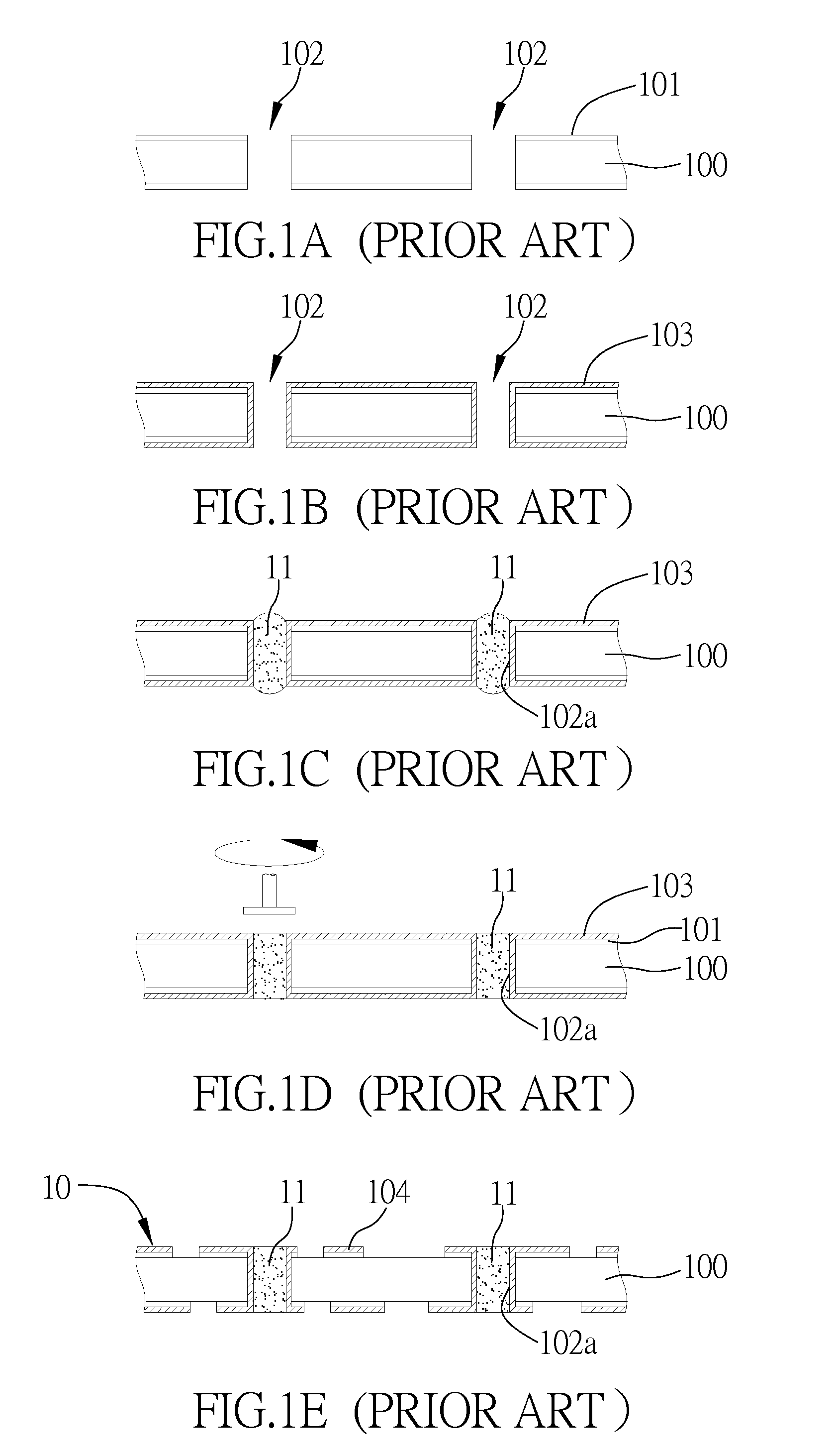
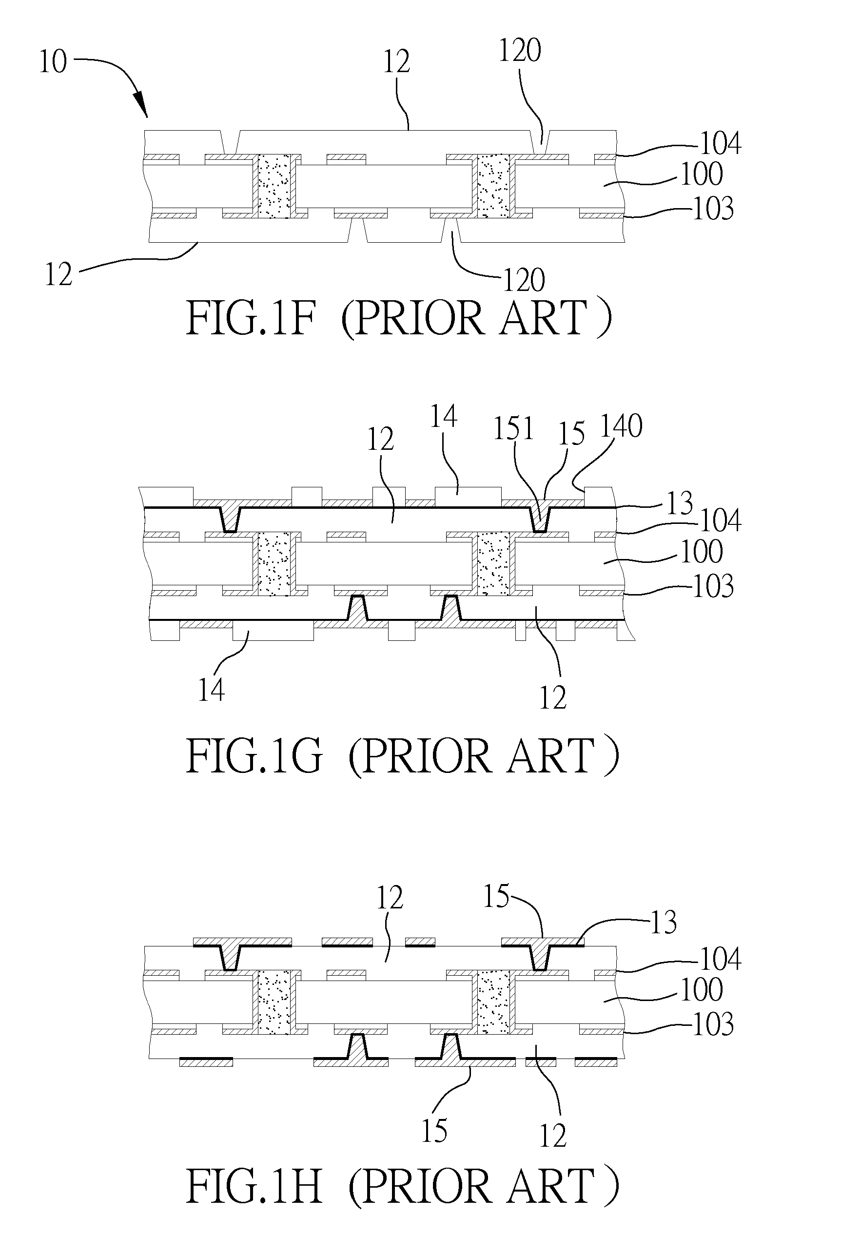
However, it is difficult to stuff the prepreg into the space between the circuits in the inner circuit layers 104.
Furthermore, the multilayer circuit board is unnecessarily thick to the detriment of miniaturization, because the core 100 occupies most of the substrate 10.

Method used


Image

  • Circuit board structure and fabrication method thereof
  • Circuit board structure and fabrication method thereof
  • Circuit board structure and fabrication method thereof

Examples


Embodiment Construction

[0040]The following illustrative embodiments are provided to illustrate the disclosure of the present invention, these and other advantages and effects can be apparent to those skilled in the art after reading the disclosure of this specification.

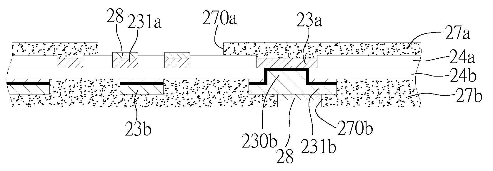
[0041]FIGS. 2A to 2R are schematic views of a circuit board structure and a fabrication method thereof in a first embodiment according to the present invention.

[0042]As shown in FIG. 2A, a carrier board 20, such as an insulating board or ceramic board, is provided.

[0043]As shown in FIG. 2B, a first conductive layer 21a is formed on the carrier board 20.

[0044]As shown in FIG. 2C, a first resist layer 22a is formed on the first conductive layer 21a, and a first opening region 220a is formed in the first resist layer 22a.

[0045]As shown in FIG. 2D, a first circuit layer 23a is formed in the first opening region 220a by an electroplating process.

[0046]As shown in FIG. 2E, the first conductive layer 21a and the first resist layer 22a thereon are...


PUM

PropertyMeasurementUnit
Structureaaaaaaaaaa
Electrical conductoraaaaaaaaaa

Abstract

Provided are a circuit board structure and a fabrication method thereof, including the steps of: forming a first circuit layer in a first dielectric layer and exposing the first circuit layer therefrom; forming a second dielectric layer on the first dielectric layer and the first circuit layer, and forming a second circuit layer on the second dielectric layer; forming a plurality of first conductive vias in the second dielectric layer for electrically connecting to the first circuit layer to thereby dispense with a core board and electroplated holes and thus facilitate miniaturization. Further, the first dielectric layer is liquid before being hardened and is formed on the first dielectric layer that enhances the bonding between layers of the circuit board and the structure.

Description

BACKGROUND OF THE INVENTION[0001]1. Field of the Invention[0002]The present invention relates to circuit board structures and fabrication methods thereof, and more particularly, to a circuit board structure without a core and a fabrication method thereof.[0003]2. Description of Related Art[0004]As electronic industry is ever-developing, a multilayer circuit board having a plurality of active elements, passive elements and circuits is provided to meet requirements of packaging for high integration and microminiaturization of a semiconductor package. More usable layout space of the multilayer circuit board in a limited area is obtained by interlayer connection technology so as to satisfy the requirements of high density of integrated circuit. A build-up method is disclosed in prior art to improve precision of the layout of a multilayer circuit board. The method comprises the steps of: Providing a core board having a plurality of inner circuit layers on the upper side and the lower sid...

Claims


Application Information

Patent Timeline
IPC IPC(8): H05K1/11H05K3/42
CPCH05K3/205H05K3/423H05K3/465H05K3/4682H05K2201/09563Y10T29/49128H01L2924/0002H05K2201/09881Y10T29/49165H01L2924/00
Inventor TSAI, KUN-CHEN
Owner UNIMICRON TECH CORP
Learn More