Busbar unit, motor, and power steering apparatus

a technology of busbar unit and power steering device, which is applied in the direction of electric cable installation, dynamo-electric machines, supports/encloses/casings, etc., can solve the problems of spark discharge and short circuit between the busbars, and achieve the effect of improving insulation performan

Active Publication Date: 2010-07-29
NIPPON DENSAN CORP
View PDF7 Cites 26 Cited by
  • Summary
  • Abstract
  • Description
  • Claims
  • Application Information

AI Technical Summary

Benefits of technology

[0008]This busbar unit according to a preferred embodiment of the present invention achieves i...

Problems solved by technology

In this case, application of a high voltage to the busbars may cause a spark discharge between the busbars, and if an ...

Method used


Image

  • Busbar unit, motor, and power steering apparatus
  • Busbar unit, motor, and power steering apparatus
  • Busbar unit, motor, and power steering apparatus

Examples


Embodiment Construction

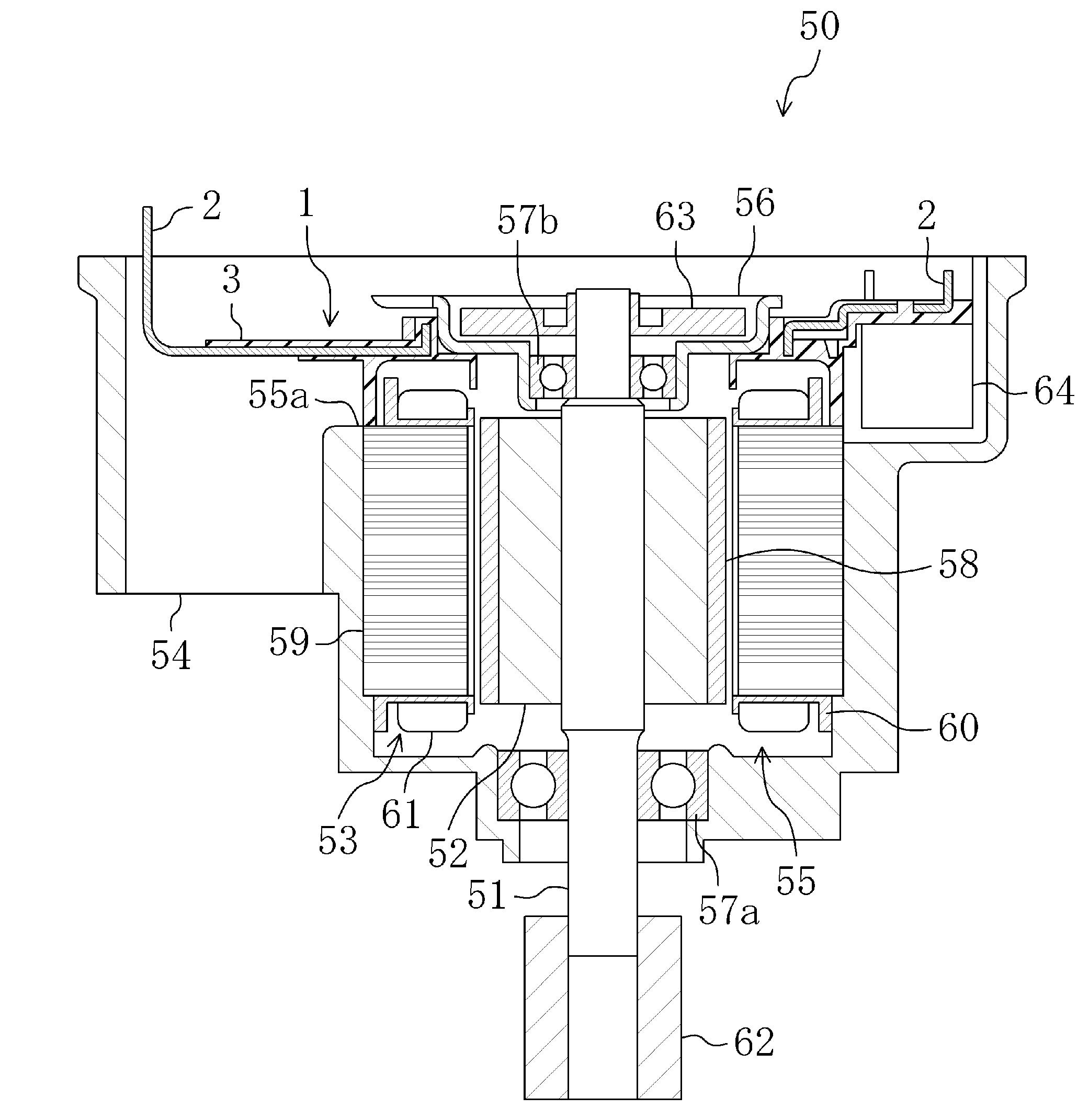
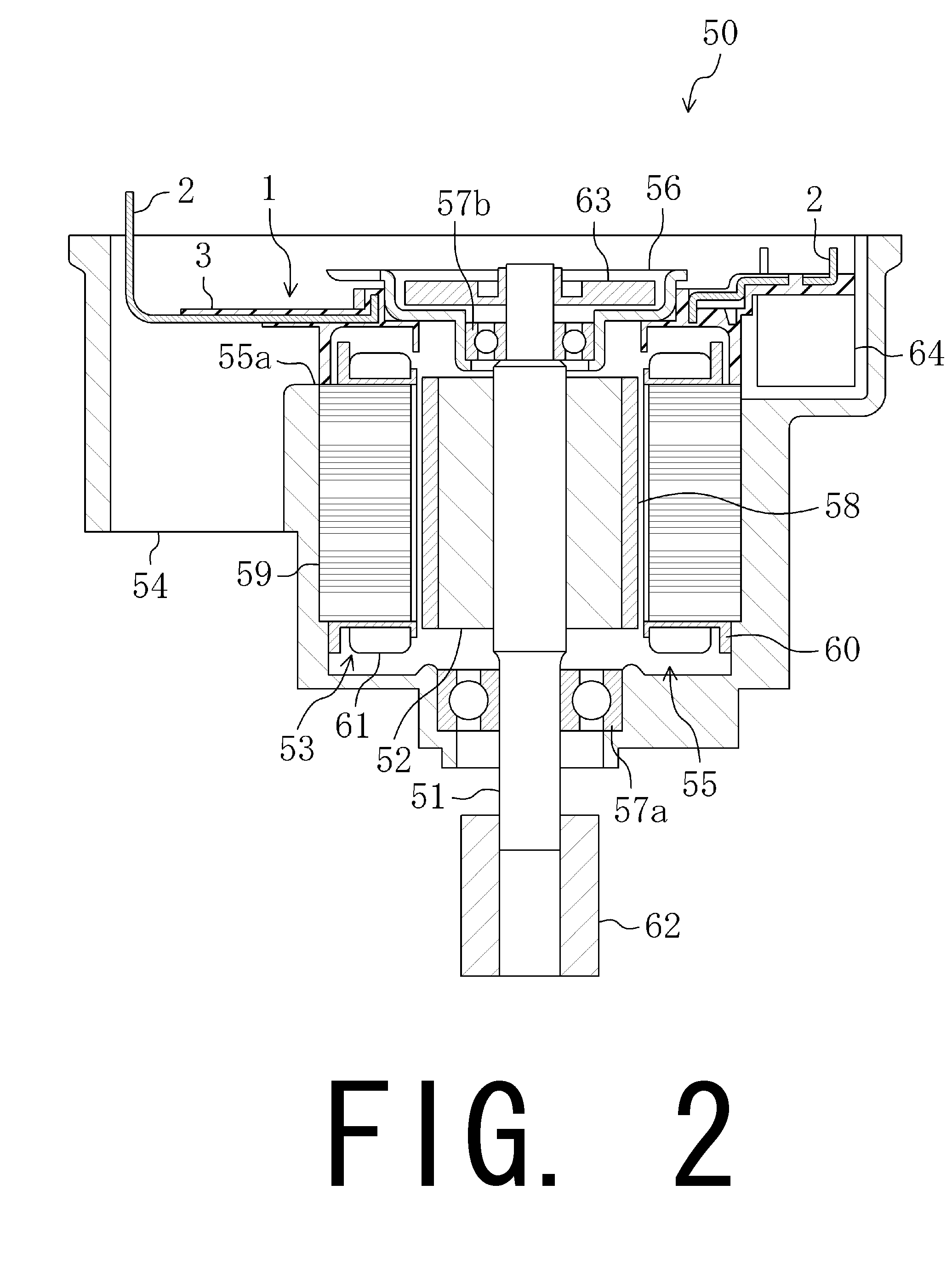
[0019]Hereinafter, preferred embodiments of the present invention will be described in detail with reference to the accompanying drawings. Note that the following description of the preferred embodiments is meant to be illustrative and not restrictive, and should not be construed to restrict the scope, applications, or purposes of the present invention. Also note that a longitudinal direction of a shaft 51 (shown, for example, in FIG. 2) and a direction parallel or substantially parallel to the longitudinal direction of the shaft 51 will be referred to as an axial direction, that a direction perpendicular or substantially perpendicular to the axial direction will be referred to as a radial direction, and that a direction in which the shaft 51 rotates will be referred to as a circumferential direction.

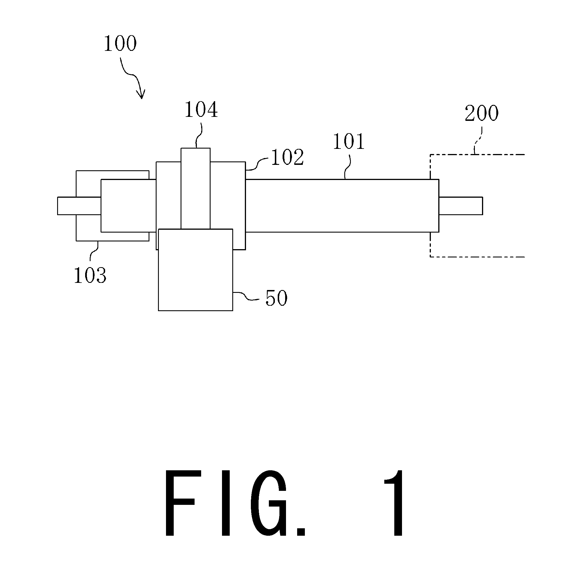
[0020]FIG. 1 is a schematic diagram of an electric power steering apparatus 100 according to a preferred embodiment of the present invention. The power steering apparatus 100 is prefera...


PUM


Abstract

A busbar unit includes a plurality of busbars including a first busbar and a second busbar, an insulating holder in which each of the busbars is arranged, and an insulating member. The holder preferably includes a first groove portion including a first opening portion arranged to receive the first busbar, and a second groove portion arranged adjacent to the first groove portion and including a second opening portion arranged to receive the second busbar. The first busbar includes a first terminal arm portion arranged to extend across the second busbar, and the insulating member is arranged between the first terminal arm portion and the second busbar.

Description

BACKGROUND OF THE INVENTION[0001]1. Field of the Invention[0002]The present invention relates to a busbar unit, a motor, and a power steering apparatus.[0003]2. Description of the Related Art[0004]In the field of motors provided with busbars, motors having a holder including a plurality of busbars arranged on a side edge of their stator in order to achieve connection of a terminal of each coil are known.[0005]The holder is made of an insulating material and formed in the shape of a doughnut. The holder includes a plurality of concentric groove portions. Each busbar is formed of a belt-shaped copper plate or the like, and is bent to assume the shape of a circular arc. Each busbar is inserted in a separate one of the groove portions of the holder. The busbar includes an arm portion extending in a radial direction. The arm portion of a busbar arranged radially inward in the holder is arranged to extend across a busbar arranged radially outward thereof.[0006]Suppose, for example, that a...

Claims


Application Information

Patent Timeline
IPC IPC(8): H02K11/00H02G5/00
CPCH02K3/522H02K5/1732H02K5/225
Inventor MIGITA, TAKAYUKISAMBUICHI, HIROSHI
Owner NIPPON DENSAN CORP
Why Eureka
Try Eureka