Supplying a signal to a light source

a technology of supply circuit and light source, which is applied in the direction of lighting apparatus, light sources, electroluminescent light sources, etc., can solve the problems of visible flicker, large ripple in output voltage, disadvantages of prior art disclosure, etc., and achieve the effect of reducing visible flicker

Active Publication Date: 2010-07-29
SIGNIFY HLDG BV
View PDF7 Cites 38 Cited by
  • Summary
  • Abstract
  • Description
  • Claims
  • Application Information

AI Technical Summary

Benefits of technology

[0006]A first aspect of the invention provides a supply circuit for supplying a voltage signal and a current signal to a light source, the supply circuit comprising at least one switch and a controller for controlling the at least one switch for reducing a value of at least one frequency component of a harmonic content of a power spectrum of the light source.
[0026]The invention solves the problem of providing a supply circuit for supplying a voltage signal and a current signal to a light source having at least reduced visible flicker (preferably non-visible flicker only), without a relatively large energy storage capacitor being required (preferably without any energy storage capacitor being required at all). The invention is further advantageous in that an energy storage capacitor can be avoided in the supply circuit.

Problems solved by technology

This prior art disclosure is disadvantageous owing to the fact that the ripple in the output voltage is still too large.
When using the converter for supplying a light source, this ripple will result in visible flicker.
The prior art disclosure is further disadvantageous owing to the fact that the converter uses an electrolytic output capacitor having a relatively large value.
Such an electrolytic output capacitor has a relatively short life time, especially at higher temperatures.

Method used


Image

  • Supplying a signal to a light source
  • Supplying a signal to a light source
  • Supplying a signal to a light source

Examples


Embodiment Construction

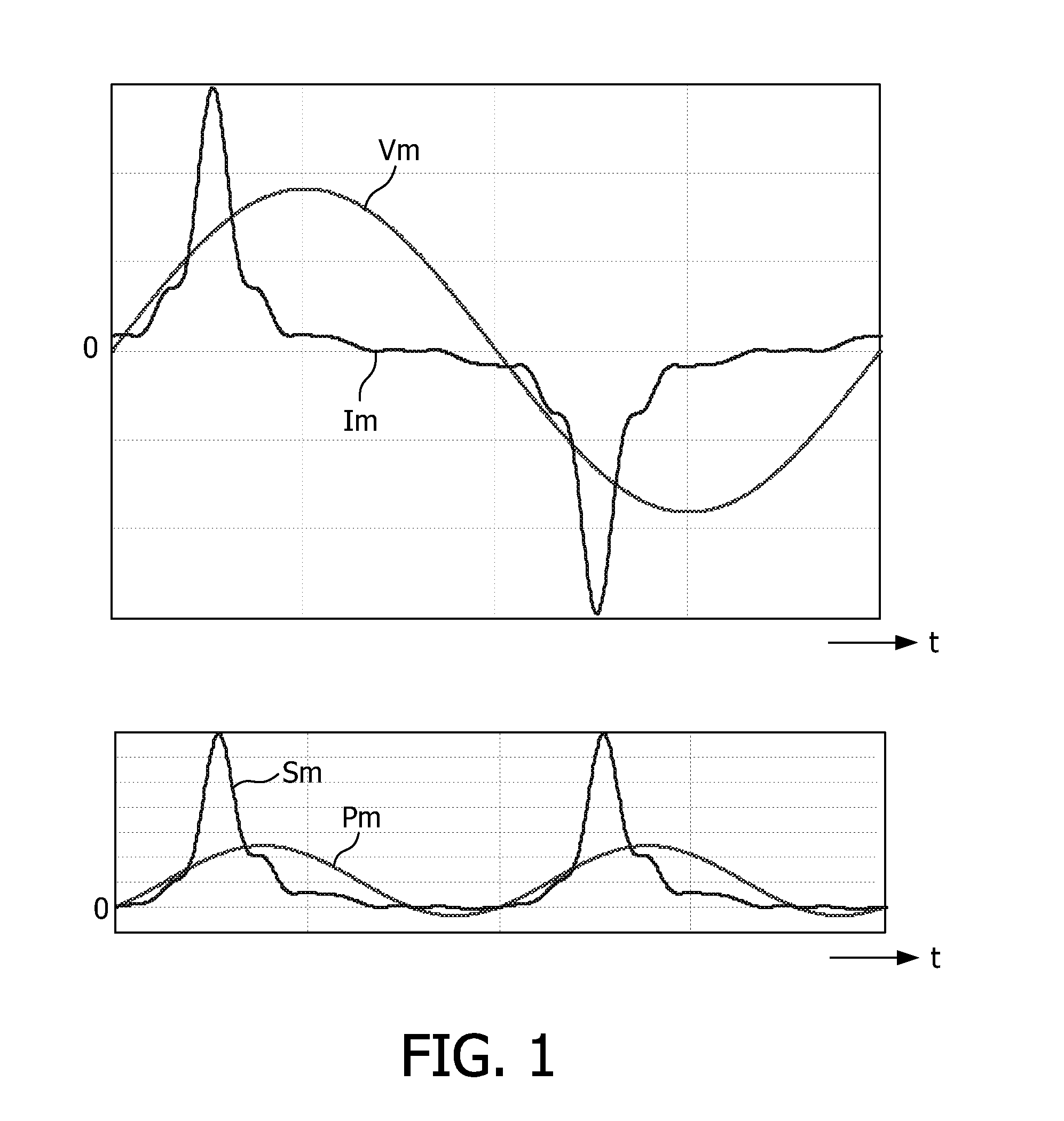
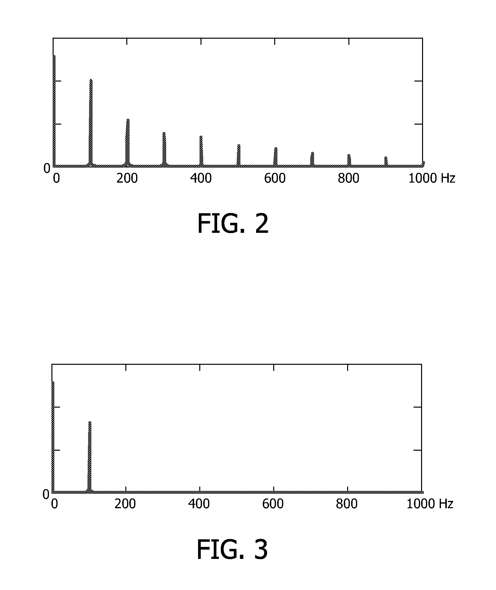
[0047]FIG. 1 shows a mains voltage Vm and a simulated mains current Im in its upper graph and a mains power Pm and a mains function Sm in its lower graph for a lamp fed by a prior art supply circuit. This current shape is typically found when an electrolytic capacitor is charged via a standard diode rectifier. The harmonic content is quite high, but this is not an issue with small lamps (for example 25 Watt) owing to the fact that there is a legislation exception for such small lamps. When applying the mains current Im without energy storage to the lamp, the light fluctuation is equal to the Sm function. To visualize the effect, this depiction in the time domain may be transferred to the frequency domain, as shown in FIG. 2.

[0048]FIG. 2 shows a frequency spectrum of the power of the lamp when fed with the distorted mains current shown in the FIG. 1. Apart from a DC light emission with a 26 Watt amplitude there is a significant component at 100 Hz with a 20 Watt amplitude, which is 7...


PUM


Abstract

Supply circuits for supplying voltage and current signals to light sources (6) comprise switches (22, 32, 42, 52) and controllers (21, 31, 41, 51) to control the switches (22, 32, 42, 52) for reducing values of frequency components of harmonic content of power spectra of the light sources (6). By switching one of the voltage and current signals or by switching signals that result in one of the voltage and current signals, the other one of the voltage and current signals can be adjusted. The power spectrum of the light source (6) may be a function of the voltage and current signals. By adjusting one of them, the power spectrum can be adjusted such that values of frequency components of the harmonic content of the power spectrum are reduced. As a result, visible flicker is reduced in the light originating from the light source (6) without the use of energy storage capacitors for reducing this visible flicker.

Description

FIELD OF THE INVENTION[0001]The invention relates to a supply circuit for supplying a voltage signal and a current signal to a light source, to a device comprising a supply circuit, to a method of supplying a voltage signal and a current signal to a light source, to a control signal for controlling a supply circuit, and to a medium for storing and comprising information for generating a control signal. Examples of such a power supply are switched mode power supplies and other power supplies. Examples of such a device are consumer products and non-consumer products. Examples of such a medium are mechanical memories and non-mechanical memories and carriers such as disks and sticks.BACKGROUND OF THE INVENTION[0002]US 2007 / 0040533 discloses in its title an input waveform control in a switching power supply and discloses in its abstract a recognition that a filter size can be reduced substantially as a power factor is permitted to deviate below unity in systematic ways. Specific, computa...

Claims


Application Information

Patent Timeline
Patent Type & Authority Applications(United States)
IPC IPC(8): H05B37/02H05B44/00
CPCH05B33/0809H05B33/0818H05B33/0815H05B45/3725H05B45/385
Inventor DEPPE, CARSTENBOEKE, ULRICHLIU, CHENYANGLUERKENS, PETER
Owner SIGNIFY HLDG BV
Why Eureka
Try Eureka