
Planar antenna

Inactive Publication Date: 2010-07-29
NATIONAL CHIAO TUNG UNIVERSITY
View PDF4 Cites 25 Cited by
  • Summary
  • Abstract
  • Description
  • Claims
  • Application Information

AI Technical Summary

Benefits of technology

[0008]The planar antenna of the present invention has one or more of the following advantages:
[0010](2) The planar antenna adopts a printed circuit board process to reduce the manufacturing cost of the antenna.

Problems solved by technology

However, present communication products tend to become increasingly smaller, and the height of antennas depends on an overall height of a product, and thus a compact and low profile design is required.
Since the distance between a horizontal arm of the antenna and the ground plane is too close, an image current produced on the ground plane 2 is in the opposite direction to the current on the antenna and thus will be offset by each other and result in poor antenna gain and radiation efficiency.

Method used


Image

  • Planar antenna
  • Planar antenna
  • Planar antenna

Examples


Embodiment Construction

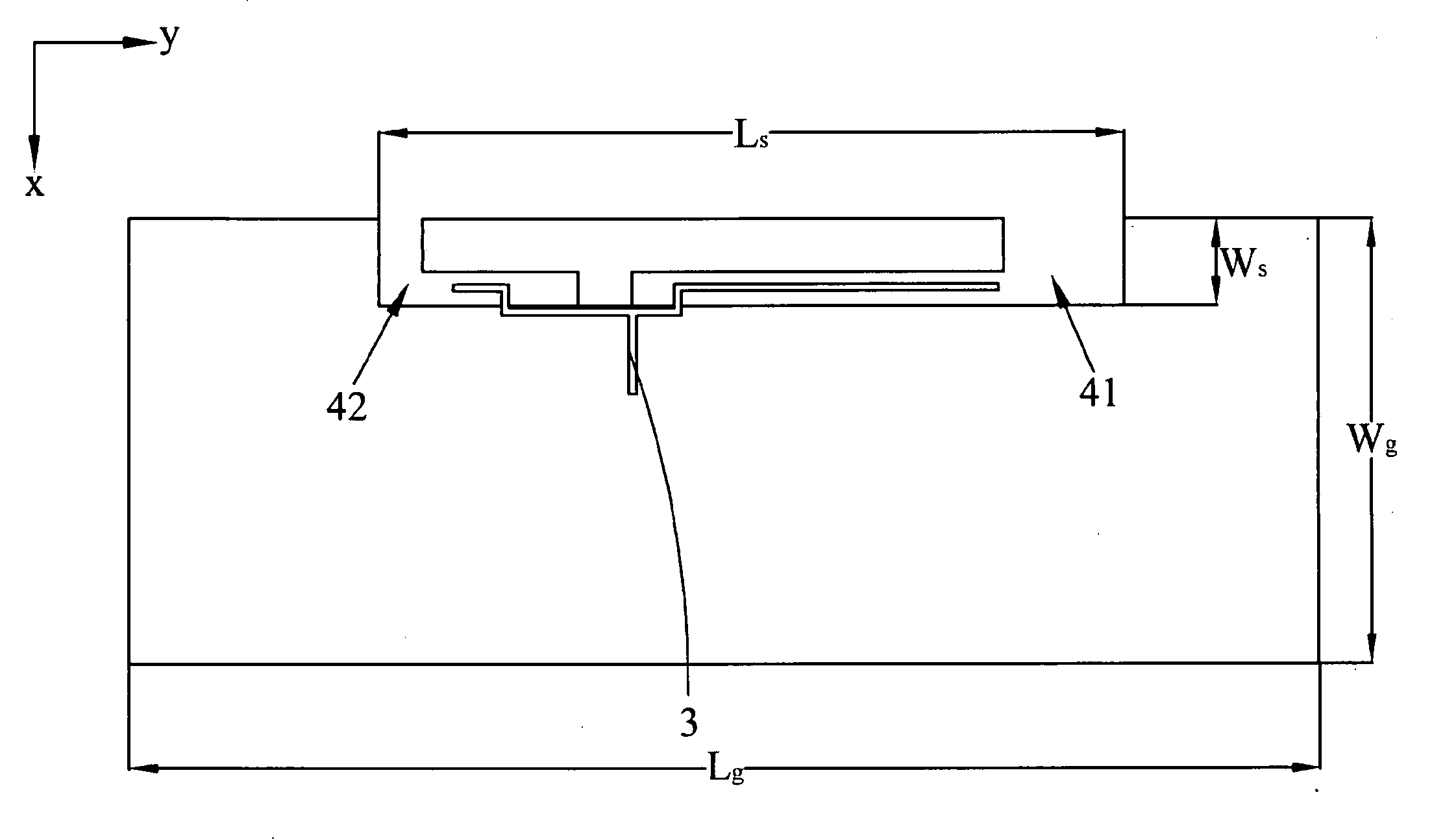
[0037]With reference to FIGS. 3 to 5 for an exploded view, a bottom view and a top view of a planar antenna in accordance with a first preferred embodiment of the present invention respectively, the planar antenna comprises a substrate 1, a ground plane 2 and a feed line 3, wherein the ground plane 2 is disposed at the bottom side of the substrate and connected to the substrate. For convenience, the arrangement and the connection of the ground plane 2 with the substrate are drawn separately (as shown in FIG. 3) and the ground plane 2 has a hollow portion 4, and the feed line 3 may be an L-shaped micro-strip feed line disposed at the top side of the substrate 1 and corresponding to the hollow portion 4 for feeding a signal, and the hollow portion 4 is a slot, wherein the planar antenna includes a first resonance frequency and a second resonance frequency, and the first resonance frequency is determined by the length of the feed line 3, and the second resonance frequency is determined...


PUM


Abstract

The present invention discloses a planar antenna including a substrate, a ground plane and a feed line. The ground plane is disposed on one side of the substrate. The ground plane includes a hollow portion. The feed line disposed on another side of the substrate and corresponding to the hollow portion for feeding a signal. The present invention also discloses a planar antenna including a substrate, a ground plane and a feed line. The ground plane is disposed on one side of the substrate. The ground plane includes a first hollow portion and a second hollow portion. The feed line is disposed on another side of the substrate and having a first branch feed portion and a second branch feed portion for feeding a signal, and the first branch feed portion and the second branch feed portion are aligned with the first hollow portion and the second hollow portion respectively.

Description

BACKGROUND OF THE INVENTION[0001]1. Field of the Invention[0002]The present invention relates to a planar antenna, in particular to an embedded multiband / wideband planar antenna having a slender area with a limited width.[0003]2. Description of the Related Art[0004]In an antenna design, a metal sheet is generally used for making a reflector or a ground plane of the antenna. After the metal sheet is disposed and a sufficient distance is kept between the metal sheet and the antenna, the antenna not only increases the antenna gain effectively, but also decreases the backward radiation of the antenna to reduce unnecessary energy losses. However, present communication products tend to become increasingly smaller, and the height of antennas depends on an overall height of a product, and thus a compact and low profile design is required. For example, the antenna of a notebook computer is generally designed and disposed at the top or both sides of a computer screen. As shown in FIG. 1, an a...

Claims


Application Information

Patent Timeline
IPC IPC(8): H01Q9/04H01Q5/10
CPCH01Q1/2266H01Q9/42H01Q9/40
Inventor CHUNG, SHYH-JONGWANG, SY-BEENLING, CHING-WEI
Owner NATIONAL CHIAO TUNG UNIVERSITY
Features
  • Generate Ideas
  • Intellectual Property
  • Life Sciences
  • Materials
  • Tech Scout
  • Unparalleled Data Quality
  • Higher Quality Content
  • 60% Fewer Hallucinations
Learn More