Color display unit

a color display unit and color technology, applied in the field of color display units, can solve the problems of low luminous efficiency of ultraviolet-excited leds, hardly satisfied response performance requirements for tv use, and all red phosphors at present have long afterglow time, etc., to achieve the effect of improving visibility and obtaining certain brightness quickly

Inactive Publication Date: 2010-07-29
SONY CORP
View PDF8 Cites 21 Cited by
  • Summary
  • Abstract
  • Description
  • Claims
  • Application Information

AI Technical Summary

Benefits of technology

[0010]On the other hand, a blue-excited red phosphor has short afterglow time, and therefore the phosphor has substantially no difficulty in that point. As a background of appearance of blue-excited white LED, progress in development of fluorescent materials is listed, which provide fluorescent light emission having high unimodal in wavelength ranges of respective primary colors. Further improvement of the fluorescent materials is still supposed in the future. Moreover, use of the white LED is advantageous in that a display grade may be improved for TV use, for example, a display color reproduction range may be increased as in the RGB monochromatic semiconductor-light-emission LED. Moreover, since only a single excitation semiconductor element, blue LED, needs to be used, reduction in cost in total is expected due to volume efficiency or the like. In this way, the blue-excited white LED is considered to have many industrial advantages. However, the white LED has the following demerits as compared with the RGB independent-light-emission LED from a viewpoint of TV use.
[0020]Particularly, when the blue LED and the blue-excited complementary-color LED are used for the light source section, and the LED are independently controlled in light emission, high luminance efficiency and a short afterglow characteristic may be obtained as compared with an ultraviolet-excited LED. Even in this case, when the blue LED and the complementary color LED are independently controlled in light emission, the quantity of light emitted by each LED may be appropriately adjusted, so that color balance may be adjusted, and change in color with time may be corrected. Particularly, when the full-color transmittable region and the partially transmittalbe region are configured without using a blue filter having low transmittance as compared with other color filters, use efficiency of light may be further increased. From these, color display may be achieved, which is high in use efficiency of light and is stable as compared with the previous type using all the RGB color filters.

Problems solved by technology

However, the ultraviolet-excited LED is low in luminous efficiency, and particularly, all red phosphors at present have long afterglow time.
Therefore, when the ultraviolet-excited LED are used to configure RGB independent-light-emission (fluorescent-light-emission) LED, response performance desired for TV use is hardly satisfied.
Particularly, since red afterglow is long, red light disadvantageously remains long as compared with other color light even after respective color LED are turned off.
However, the semiconductor-light-emission red LED disadvantageously has a property of large temperature dependence of light emission output, and has a property that when the LED becomes hot, light emission output is decreased to approximately half.
Furthermore, the red LED has forward voltage drop of about 2 volts, which is about 1 volt low as compared with that of another color element (blue or green), about 3 to 4 volts, leading to a difficulty that circuit setting may not be made common between the color elements.
Consequently, handling of circuits is difficult, and circuit cost is high.
However, actually, such change does not necessarily uniformly occur because of, for example, change in excitation wavelength of the blue light as an excitation source.
Therefore, RGB balance of the mixed white light is changed, resulting in a difficulty of change in color tone.
Since such balance is lost within one LED component, the balance may not be adjusted by the LED itself.

Method used


Image

  • Color display unit
  • Color display unit
  • Color display unit

Examples


first embodiment

[Basic Configuration of Color Display Unit]

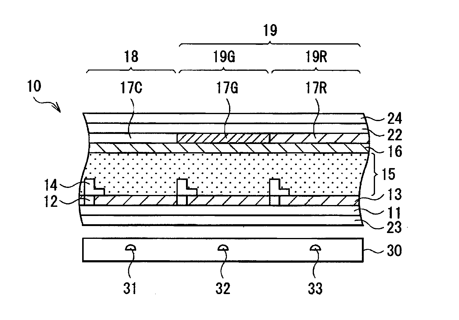
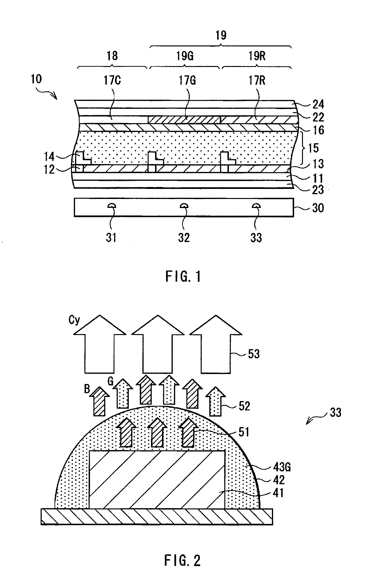
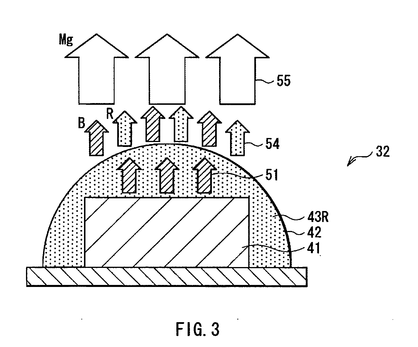
[0049]FIG. 1 shows a basic configuration example of a color display unit according to a first embodiment of the invention. The color display unit has a display panel 10, and a backlight 30 opposed to the display panel 10 on a back side of the display panel 10. The backlight 30 has three kinds of LEDs, i.e., blue LED 31, magenta LED 32, and cyan LED 33, each LED being able to be independently controlled in light emission. The blue LED 31 is a semiconductor light emitting element including a GaN (gallium nitride) based semiconductor material or the like.

[0050]In the embodiment, the display panel 10 corresponds to a specific example of the display section according to the invention. The backlight 30 corresponds to a specific example of the light source section according to the invention.

[0051]The display panel 10 performs desired color display by controlling the transmissivity of the light irradiated from the backlight 30. The display panel 10...

second embodiment

[0082]Next, a color display unit according to a second embodiment of the invention is described. Substantially the same components as in the color display unit according to the first embodiment are marked with the same reference numerals or signs, and description of them is appropriately omitted.

[Basic Configuration of Color Display Unit]

[0083]FIG. 6 shows a configuration example of the color display unit according to the present embodiment. In this color display unit, the partially transmittable region 19 (the red transmittable region 19R and the green transmittable region 19G) of the color display unit shown in FIG. 1 is replaced by a yellow transmittable region 19Y. In addition, a yellow color filter 17Y is provided in place of the red filter 17R and the green filter 17G. The yellow filter 17Y is transparent to yellow light, namely, transparent to red light and green light, and opaque to blue light. The yellow filter 17Y is provided in correspondence to the yellow transmittable r...

third embodiment

Modification of Third Embodiment

[0104]While FIG. 16 shows a configuration where red and green, two kinds of color transmittable regions (the red transmittable region 19R and the green transmittable region 19G) are provided as the partially transmittable region 19, and a portion corresponding to the previous blue transmittable region is made transparent to be the full-color transmittable region 18, a portion to be made transparent may not be the portion corresponding to the blue region.

[0105]FIG. 20 shows a display device different from the display device having the previous structure as shown in FIG. 10, in that it has a display panel 10B using a transparent filter 17C in place of the green filter 17G. The transparent filter 17C is used, thereby a portion corresponding to the green transmittable region 19G is made transparent to be the full-color transmittable region 18. The display device has red and blue, two kinds of color transmittable regions (the red transmittable region 19R a...


PUM


Abstract

A color display unit is provided, which allows color display to be performed with high efficiency in utilizing light as compared with a prior type using all of RGB color filters. The color display unit includes a light source section having plural kinds of color LEDs, and includes a display section controlling transmissivity of light from the light source section in synchronization with light emission control by the light source section, to achieve desired color display. The display section has a full-color transmittable region and a partially transmittable region. The full-color transmittable region allows all color components of the light to be transmitted, while the partially transmittable region inhibits passage of one or more in the color components of the light. The display section controls the transmissivity of the light independently for each of the full-color transmittable region and the partial transmittable region.

Description

BACKGROUND OF THE INVENTION[0001]1. Field of the Invention[0002]The present invention relates to a color display unit performing color display using a plurality of LED (Light Emitting Diodes).[0003]2. Description of Related Art[0004]In the past, a color display unit includes a combination of a transmittable color display panel such as color liquid crystal panel and a backlight (see Japanese Unexamined Patent Application Publication No. 2007-4099). The color display panel typically uses three kinds of color filters, i.e., an R (red) filter, a G (green) filter, and a B (blue) filter. A backlight using an LED light source is generally known. In a previous type of the backlight using the LED light source, three kinds of light emitting diodes, i.e., R (red) LED, G (green) LED, and B (blue) LED are used, each LED including a semiconductor element emitting monochromatic light by itself. In this backlight type, three kinds of monochromatic LED, red LED, green LED and blue LED, are combined,...

Claims


Application Information

Patent Timeline
Patent Type & Authority Applications(United States)
IPC IPC(8): G09G3/32
CPCG02F1/133514G02F1/133603G02F2001/133601G02F2001/133614G09G2320/0242G09G3/3413G09G3/3607G09G2300/0452G09G2310/0235G02F2201/52G02F1/133601G02F1/133614
Inventor FURUKAWA, NORIMASA
Owner SONY CORP
Why Eureka
Try Eureka