
Projection method

a projection method and video projection technology, applied in the field of projection methods, can solve the problems of physical motion of users and the use of a small proportion of the usable projection area of the video projection device, and achieve the effect of small size and weigh

Inactive Publication Date: 2010-07-29
ASHLEY KALMAN
View PDF7 Cites 24 Cited by
  • Summary
  • Abstract
  • Description
  • Claims
  • Application Information

AI Technical Summary

Benefits of technology

"The invention provides a method for displaying a visual image on a display surface using a video projector. The method involves determining the location on the display surface of the projected image produced by the video projector. The method then selects the part of the visual image that corresponds to the location. The method can be used in a variety of situations, such as when the video projector is moving or the display surface is uneven. The method ensures that the projected image always looks good, regardless of the position of the video projector. The invention also provides a navigation system based on the relationship between the video projector and the projected image. The method can be implemented using a camera or position sensors on the video projector. The invention can be used with different types of projectors, such as standalone or handheld. The visual image can be a still image or a moving image, and can be computer-generated or read from a memory."

Problems solved by technology

The limitation on the use of these projectors is that they are susceptible to the physical motion of the user and require the user to control the projected content by inputting commands with a keypad or touch screen.
The system described in the prior art has the disadvantage that, in order to produce a static image, only a small proportion of the usable projection area of the video projector is used, because sufficient unused space must be provided within the projected image to accommodate movement of the video projector relative to the static image.

Method used


Image

  • Projection method
  • Projection method
  • Projection method

Examples


Embodiment Construction

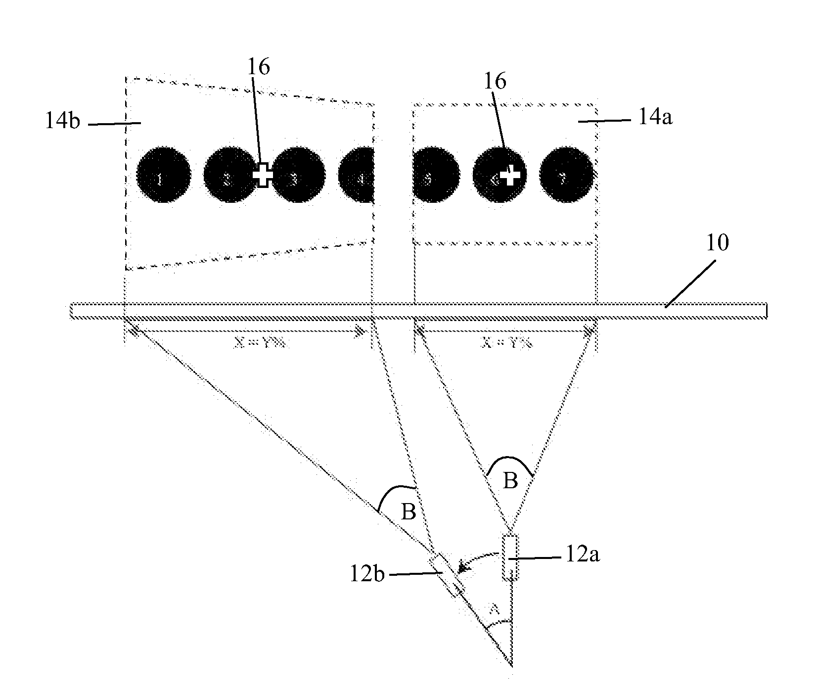
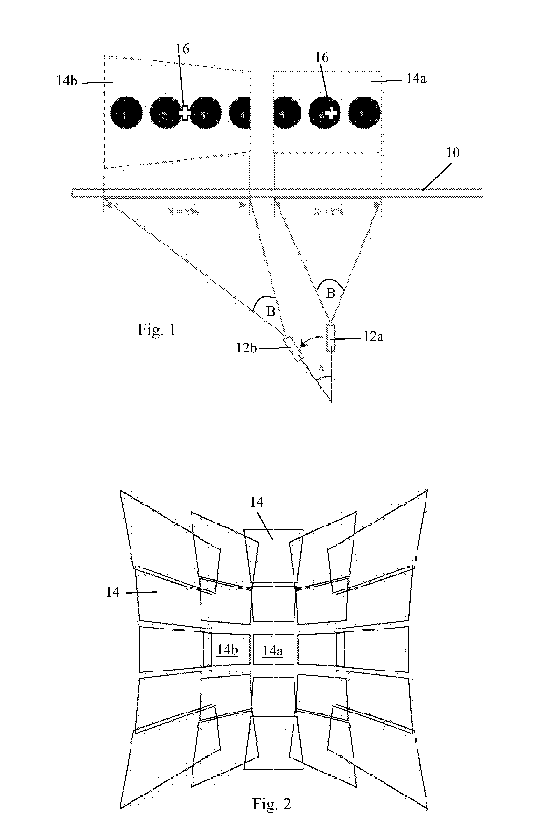
[0029]Referring to FIG. 1, the invention provides a method of displaying a visual image, such as a digital image, on a display surface 10, such as a screen or wall, using a video projector 12. The total area occupied by the complete visual image on the display surface 10 is larger than the area of the projected image 14 produced by the video projector 12. The method comprises determining the location 14a, 14b on the display surface 10 of the projected image produced by the video projector 12. Subsequently, a part of the complete visual image is selected which corresponds in position within the visual image to the location of the projected image 14a, 14b on the display surface 10. The image part is displayed as the projected image 14a, 14b.

[0030]In FIG. 1, the visual image is a series of numbered circles (1 to 9). The figure shows the video projector 12 in two positions 12a, 12b, with an angle A between the two positions. The video projector 12 and the display screen 10 are shown in...


PUM


Abstract

There is disclosed a method of displaying a visual image, such as a digital image, on a display surface (10), such as a screen or wall, using a video projector (12). The total area occupied by the complete visual image on the display surface (10) is larger than the area of the projected image (14) produced by the video projector (12). The method comprises determining the location (14a,14b) on the display surface (10) of the projected image produced by the video projector (12). Subsequently, a part of the complete visual image is selected which corresponds in position within the visual image to the location of the projected image (14a,14b) on the display surface (10). The image part is displayed as the projected image (14a,14b). The method has the advantage that all of the projected image (14) can be used to display the visual image, in parts. The video projector (12) can be moved to display any desired region of the complete visual image.

Description

FIELD OF THE INVENTION[0001]This invention relates to a method of projecting visual information, and in particular to a method of interacting with the projected visual information.[0002]BACKGROUND TO THE INVENTION[0003]It is desirable to make digital visual media more accessible for mobile use through the use of projection technologies, such as laser or LED projectors. The limitation on the use of these projectors is that they are susceptible to the physical motion of the user and require the user to control the projected content by inputting commands with a keypad or touch screen.[0004]U.S. Pat. No. 6,764,185 discloses an interactive display system in which a handheld video projector includes a sensor, which senses the position and orientation of the video projector relative to a display surface. As the video projector is moved, the image projected by the video projector is adapted in order to produce a stable image on the display surface. The image projected by the video projector...

Claims


Application Information

Patent Timeline
Patent Type & Authority Applications(United States)
IPC IPC(8): H04N9/31
CPCH04N5/74G06F3/0346H04N9/3194H04N9/3185H04N5/2628H04N5/7441
Inventor ASHLEY, ADRIAN ISTVANSLOCOMBE, DAVID HOWELLS LLEWELLYN
Owner ASHLEY KALMAN
Learn More