[0023]The present invention makes it possible to dry
printing ink and to avoid adhesion of printed materials with each other securely and easily by utilizing Nano sized high-temperature dryness steam.BEST
MODES FOR CARRYING OUT THE INVENTION
[0024]Hereinafter, embodiments of the present invention will be described in detail by referring to the drawings.
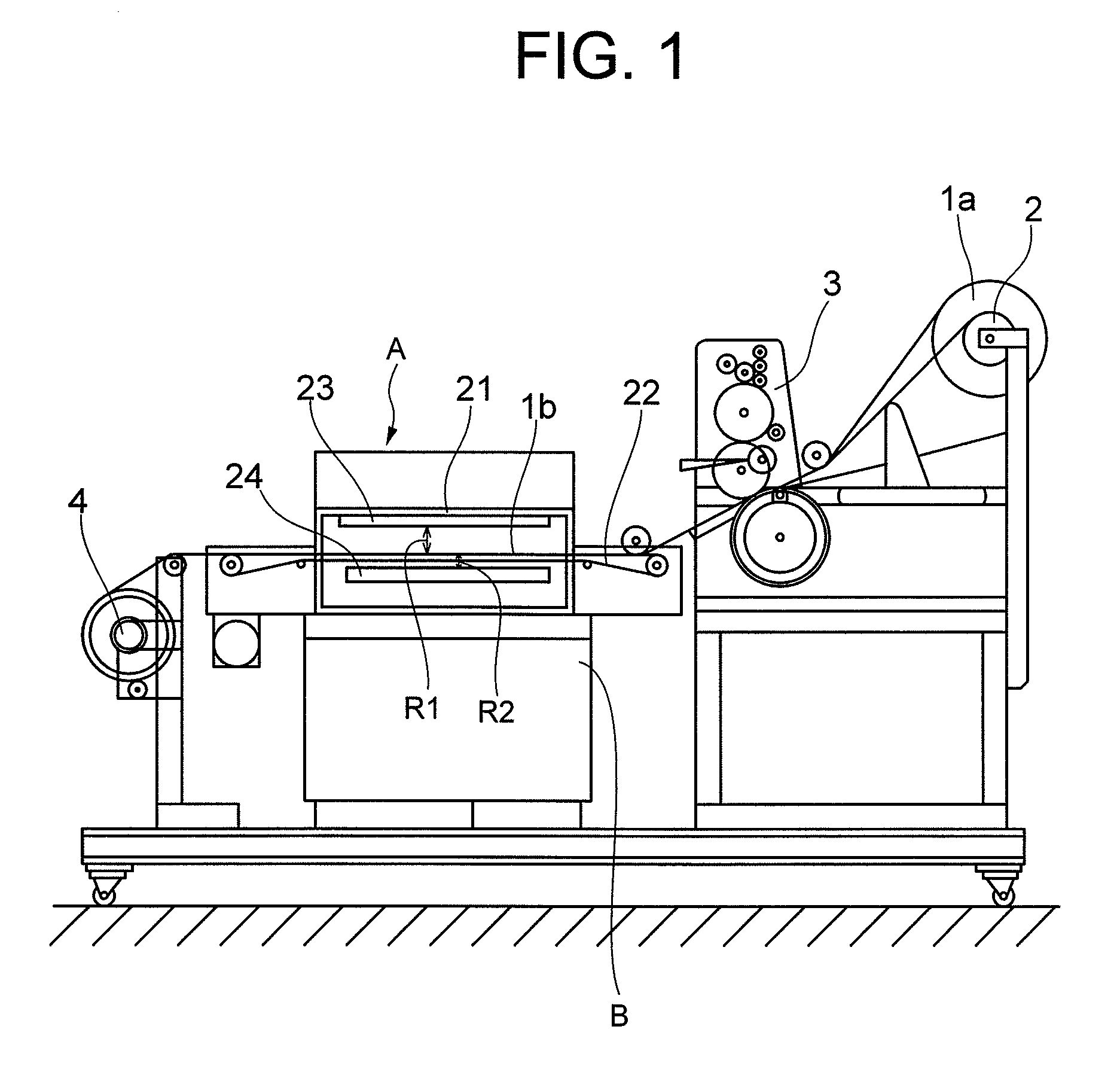
[0025]FIG. 1 shows a printing device to which a printed material drying apparatus according to the embodiment of the present invention is applied. The printing device shown in FIG. 1 is a device which prints on a continuous rolled paper, and it is structured to: hold a printing paper 1a to a feeding roller 2; perform printing on a print side of the printing paper 1a fed out from the teeding roller 2 at a printing section 3; let already printed paper 1b go through the printed material drying apparatus A according to the embodiment of the present invention; and takes up dry-processed paper 1 onto a take-up roller 4.
[0026]As shown in FIG. 1, the printed material drying apparatus A according to the embodiment of the present invention is an apparatus which: accepts the printed paper 1b printed by the printing section 3 into inside a drying chamber 21; dries the ink on the printed material 1b quickly by Nano sized high-temperature dryness steam; and sends out the dried printed material 1b towards the take-up roller 4. As shown in FIG. 1-FIG. 3, the printed material drying apparatus A includes a steam generating device 5, a cluster generating device 6, and an exciting device 7.
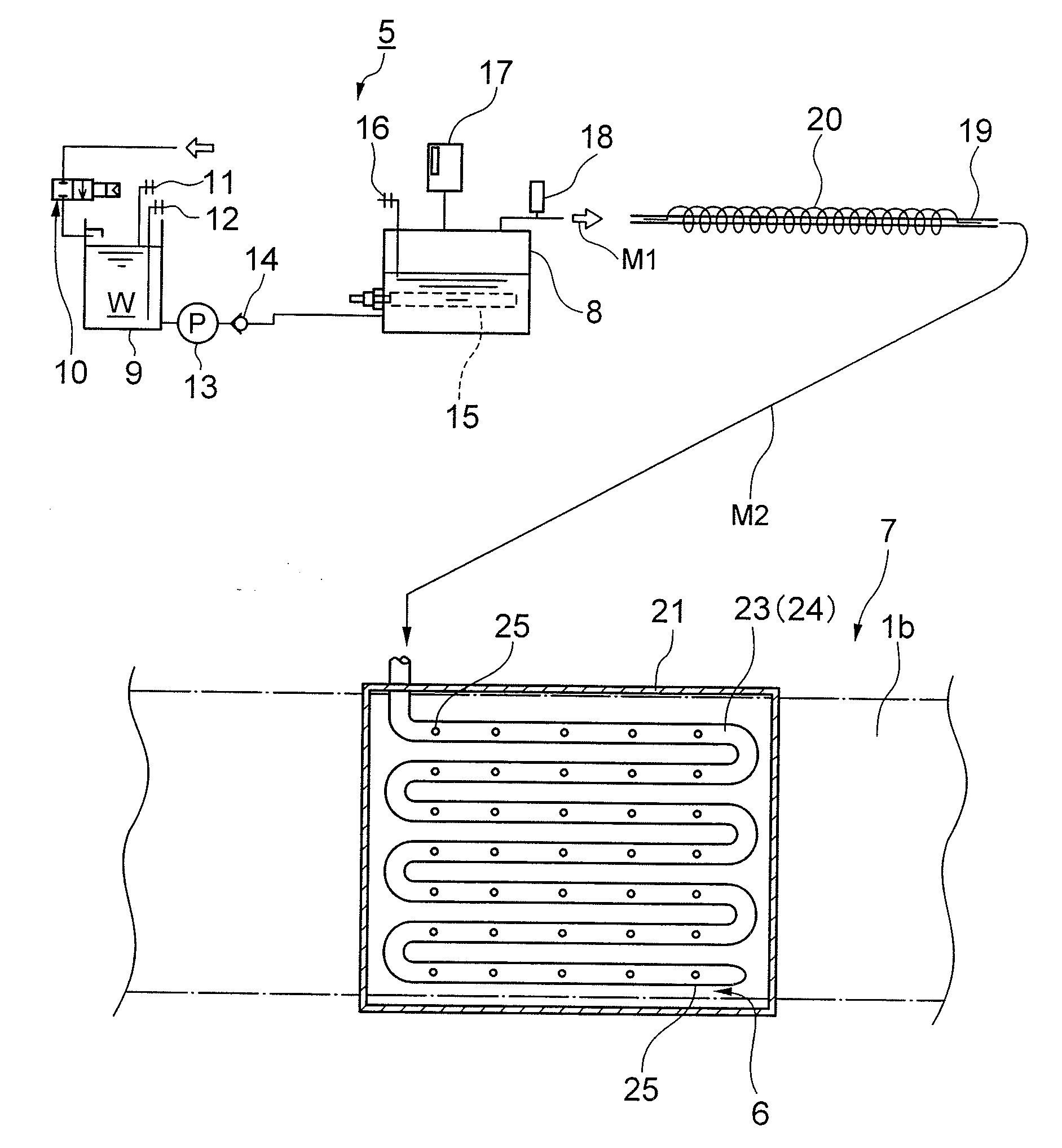
[0027]The steam generating device 5 generates high-temperature dryness steam. Specifically, as shown in FIG. 3, the steam generating device 5 includes a boiler 8 and a
water supply tank 9. Water is supplied to the
water supply tank 9 via a water feed valve 10, and the water feed valve 10 is controlled by an upper-limit sensor 11 and a lower-limit sensor 12 to accumulate water W of a set amount inside the
water supply tank 9. The water W is fed to the boiler 8 from the water supply tank 9 by a pump 13 through a nonreturn valve 14, and the boiler 8 includes a heater 15 for heating the supplied water. The boiler 8 heats the water by the heater 15 to generate high-temperature saturated steam M1. Reference numeral 16 is a sensor for detecting a
water level within the boiler 8, 17 is a pressure
relief valve for keeping the pressure within the boiler 8 to a specific pressure, and 18 is a feeding valve which takes out the high-temperature saturated steam M1 from the boiler 8. Further, on the output side of the boiler 8, a
pipe 19 for letting through the high-temperature saturated steam M1 and a tubular heater 20 wound around the
pipe 19 are provided. High-temperature dryness steam M2 is obtained by letting through the high-temperature saturated steam M1 within the
pipe 19 that is heated by the tubular heater 20. Note that the boiler 8 and the water supply tank 9 of the steam generating device 5 are merely presented as a way of examples, and the structures thereof are not limited to those shown in the drawing. The steam generating device 5 may be a type other than the one shown in the drawing. The point is that the steam generating device 5 may be of any types, as long as it is in a structure capable of generating the high-temperature saturated steam M1.
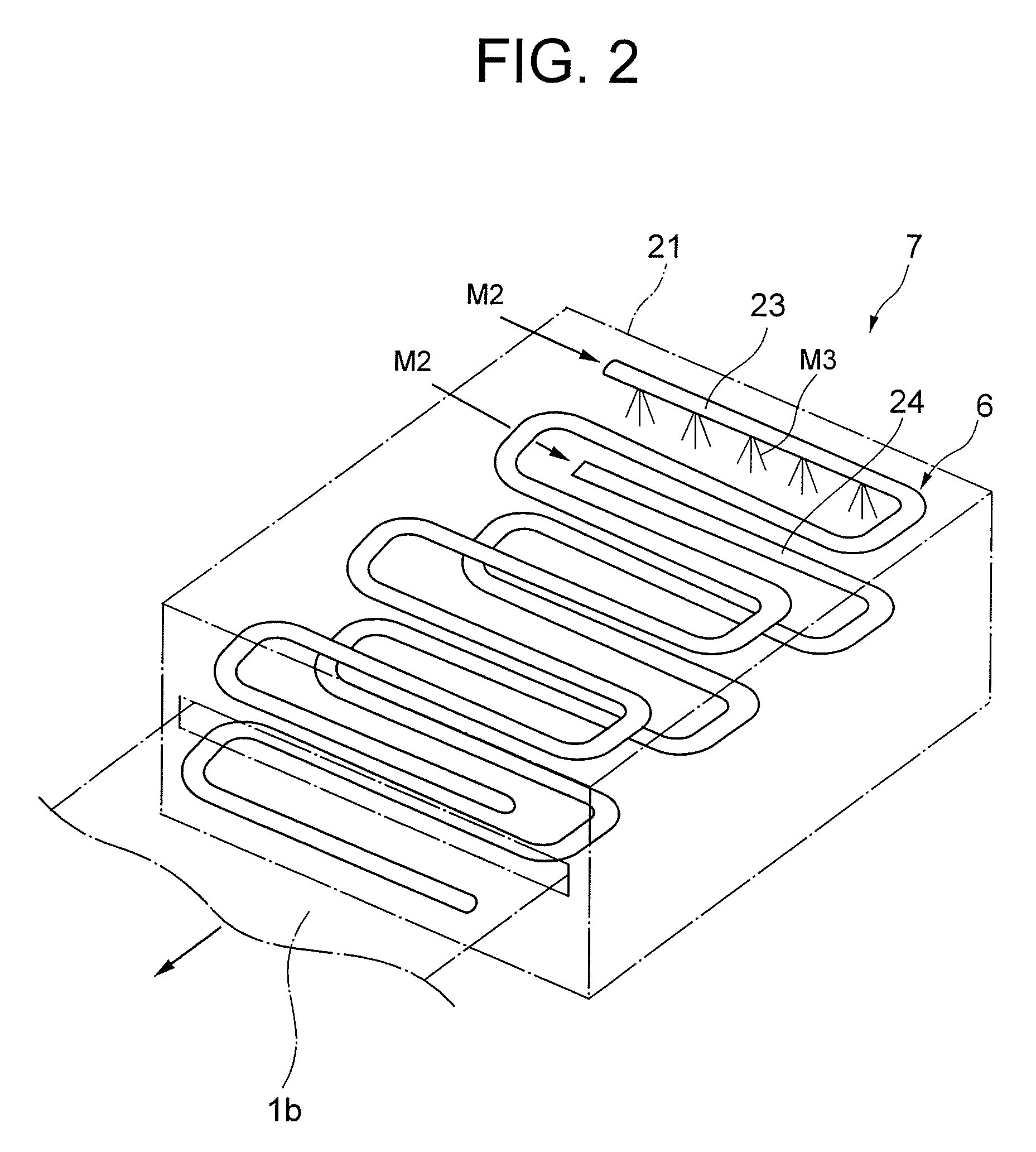
[0028]The cluster generating device 6 and the exciting device 7 are placed inside the drying chamber 21 to which the already printed paper 1b is fed by a feeding roller 22. The cluster generating device 6 and the exciting device 7 will be described in detail. That is, pipes 23 and 24 are placed in a vertical direction by sandwiching the feeding roller 22 within the drying chamber 21 as shown in FIG. 1 and FIG. 2. As shown in FIG. 3, a plurality of nozzles 25 are opened in the pipes 23 and 24 towards the printed paper 1b that runs within the drying chamber 21. The cluster generating device 6 obtains Nano sized high-temperature dryness steam M3 made as a cluster is generated to the Nano oder through spraying the high-temperature dryness steam M2 from the nozzles 25 of the pipes 23 and 24 (see FIG. 2). The pipe 23 is placed on the print side of the printed paper 1b, and the pipe 24 is placed on the back face side of the printed material 1b. Distance R2 from the pipe 24 to the printing paper 1 is set to be shorter than distance R1 that is from the pipe 23 to the printing paper 1 (R1>R2). The distances from the pipes 23, 24 to the printed paper 1b are not limited to those illustrated in the drawing but may be changed as appropriate in accordance with the kind of the printed paper 1b. In FIG. 2, it is illustrated to spray the Nano sized high-temperature dryness steam M3 from a part of the pipe 23. However, it is sprayed from the whole length of the pipes 23 and 24.

