
System and method for suppressing combustion instability in a turbomachine

a turbomachine and combustion instability technology, applied in the field of turbomachines, can solve problems such as catastrophic damage, combustion instability/dynamics, hardware damage, etc., and achieve the effect of suppressing combustion instability

Inactive Publication Date: 2010-08-05
GENERAL ELECTRIC CO
View PDF18 Cites 21 Cited by
  • Summary
  • Abstract
  • Description
  • Claims
  • Application Information

AI Technical Summary

Benefits of technology

"The invention is a system and method for suppressing combustion instability in a turbomachine. It includes a pre-mixer that receives fuel and air, which are combined and discharged into the combustion chamber. The system creates a combustion asymmetry to suppress combustion instability in the turbomachine. The technical effect is to improve the stability and efficiency of the turbomachine's combustion process."

Problems solved by technology

Combustion instability / dynamics is a phenomenon in turbomachines utilizing lean pre-mixed combustion.
Under certain operating conditions, the combustion component and the acoustic component couple to create a high and / or low frequency dynamic field that has a negative impact on various turbomachine components with a potential for hardware damage.
The dynamic field passing from the combustor may excite modes of downstream turbomachine components as can lead to catastrophic damage.
While effective at suppressing combustion instability, avoiding these operating conditions restricts the overall operating envelope of the turbomachine.
More specifically, fluctuations in the fuel-air ratio are known to cause combustion dynamics that lead to combustion instability.
While both of the above approaches are effective at suppressing combustion instability, avoiding various operating conditions restricts an overall operating envelope of the turbomachine while manipulating the fuel-air ratio requires a complex control scheme, and may lead to less than efficient combustion.

Method used


Image

  • System and method for suppressing combustion instability in a turbomachine
  • System and method for suppressing combustion instability in a turbomachine
  • System and method for suppressing combustion instability in a turbomachine

Examples


Embodiment Construction

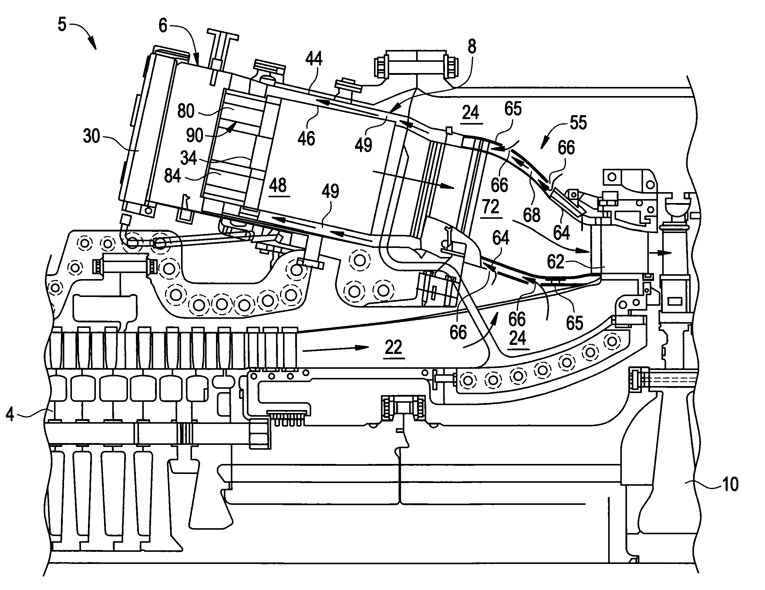
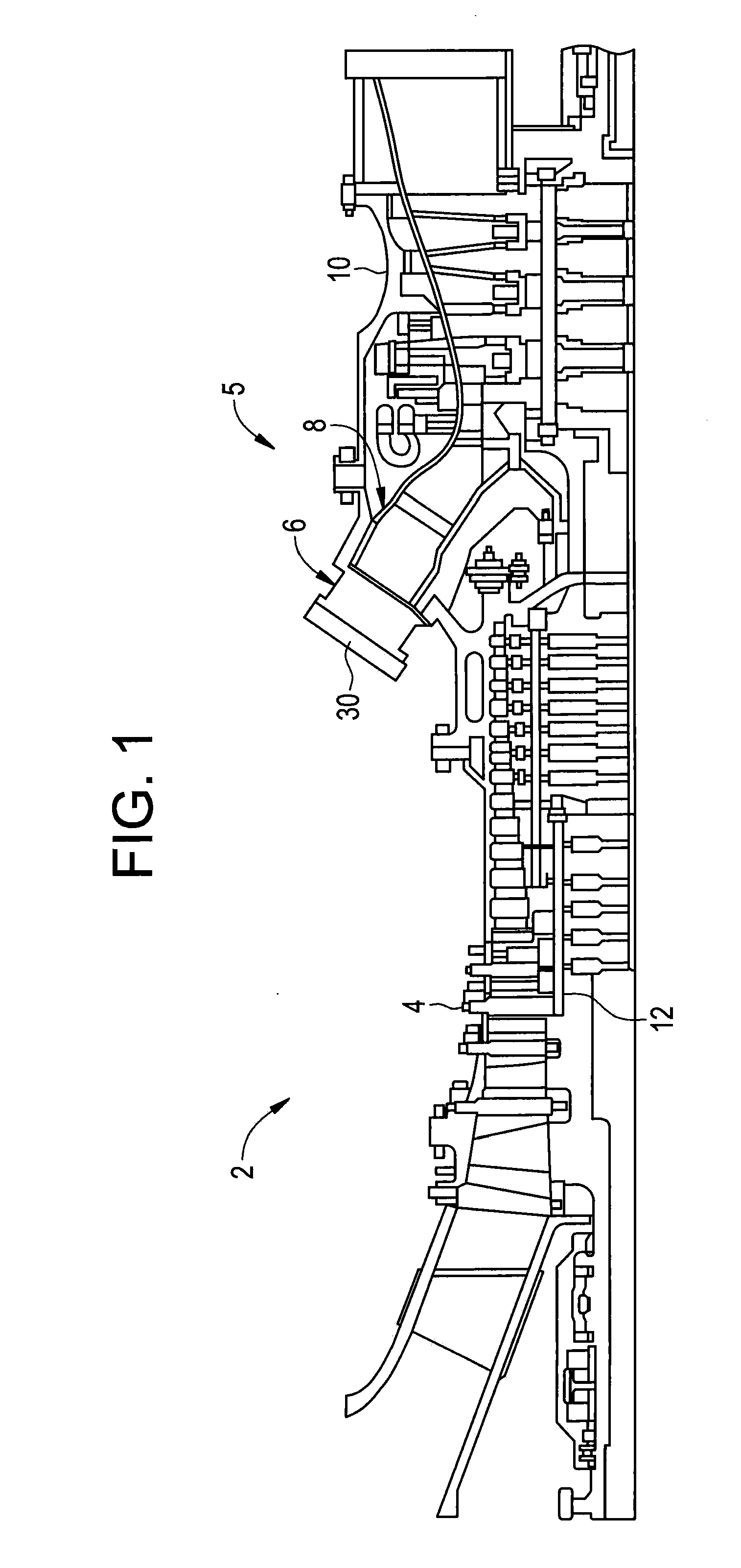
[0016]With initial reference to FIG. 1, a turbomachine constructed in accordance with exemplary embodiments of the invention is generally indicated at 2. Turbomachine 2 includes a compressor 4 and a combustor assembly 5 having a plurality of combustors, one of which is indicated at 6. In the exemplary embodiment shown, combustor 6 is provided with a fuel nozzle or injector assembly housing 8. Turbomachine 2 also includes a turbine 10 and a common compressor / turbine shaft 12. In one embodiment, turbomachine 2 is a PG9371 9FBA Heavy Duty Gas Turbine Engine, commercially available from General Electric Company, Greenville, S.C. Notably, the present invention is not limited to any one particular engine and may be used in connection with other gas turbine engines.

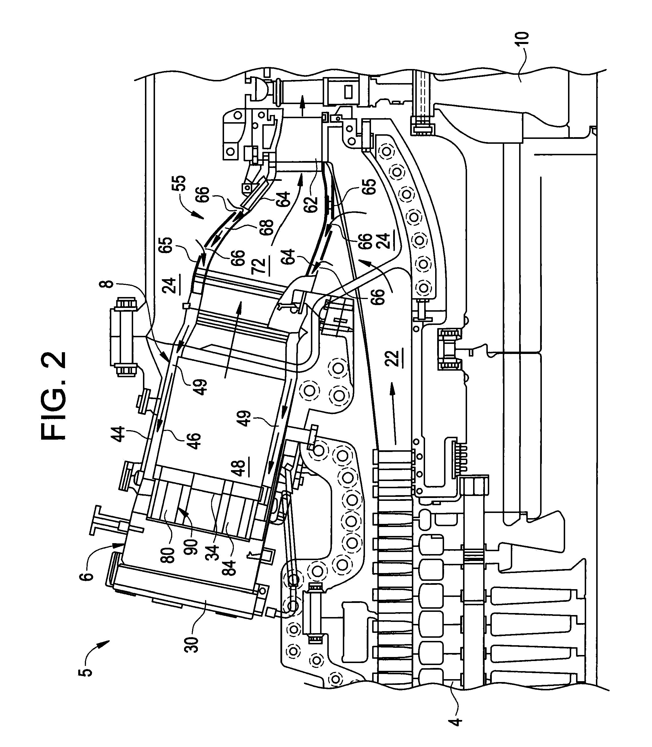
[0017]As best shown in FIG. 2, combustor 6 is coupled in flow communication with compressor 4 and turbine 10. Compressor 4 includes a diffuser 22 and a compressor discharge plenum 24 that are coupled in flow communication with e...


PUM


Abstract

A system for suppressing combustion instability in a turbomachine includes at least one combustion chamber operatively connected to the turbomachine, and at least one pre-mixer mounted to the at least one combustion chamber. The at least one pre-mixer is configured to receive an amount of fuel and an amount of air that is combined and discharged into the at least one combustion chamber. In addition, the turbomachine includes a combustion instability suppression system operatively associated with the at least one pre-mixer. The combustion instability suppression system is configured to create a combustion asymmetry. The combustion asymmetry facilitates combustion instability suppression in the turbomachine.

Description

BACKGROUND OF THE INVENTION[0001]The subject matter disclosed herein relates to the art of turbomachines and, more particularly, to a system and method for suppressing combustion instability / dynamics in a turbomachine.[0002]Combustion instability / dynamics is a phenomenon in turbomachines utilizing lean pre-mixed combustion. Depending on the nature of excitation of combustion chamber modes combustion instability can be low / high frequency. A low frequency combustion dynamics field is caused by excitation of axial modes, whereas a high frequency dynamic field is generally caused by the excitation of radial and azimuthal modes of the combustion chambers by the swirling flames and is commonly referred to as screech. The dynamic field created includes a combustion field component and an acoustic component that pass along a combustor during combustion. Under certain operating conditions, the combustion component and the acoustic component couple to create a high and / or low frequency dynami...

Claims


Application Information

Patent Timeline
Patent Type & Authority Applications(United States)
IPC IPC(8): F02C1/00
CPCF23R2900/00014F23R3/10
Inventor SINGH, KAPIL KUMARHAN, FEIMCMANUS, KEITH ROBERTSRINIVASAN, SHIVAKUMARKIM, KWANWOO
Owner GENERAL ELECTRIC CO
Learn More