Laser cutting system

a cutting system and laser cutting technology, applied in metal-working equipment, welding equipment, manufacturing tools, etc., can solve the problems of exacerbate the occurrence of restenosis or thrombosis, constrictions or blockages reoccur, and are particularly susceptible to these effects, so as to reduce or eliminate heat and oxygen related changes to the mechanical characteristics of the material

Inactive Publication Date: 2010-08-05
ABBOTT CARDIOVASCULAR
View PDF86 Cites 103 Cited by
  • Summary
  • Abstract
  • Description
  • Claims
  • Application Information

AI Technical Summary

Benefits of technology

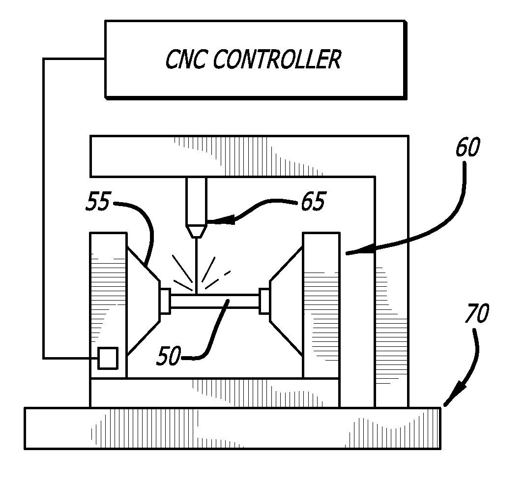
[0021]In its broadest aspect, the present invention includes a laser cutting system having a chamber configured to provide a controlled environment while the laser is being used to cut a pattern into a material to reduce or eliminate heat and oxygen related changes to the mechanical characteristics of the material. The chamber includes means for providing a gas to the controlled environment within the chamber, as well as a means for exhausting gas and cutting debris from the chamber.
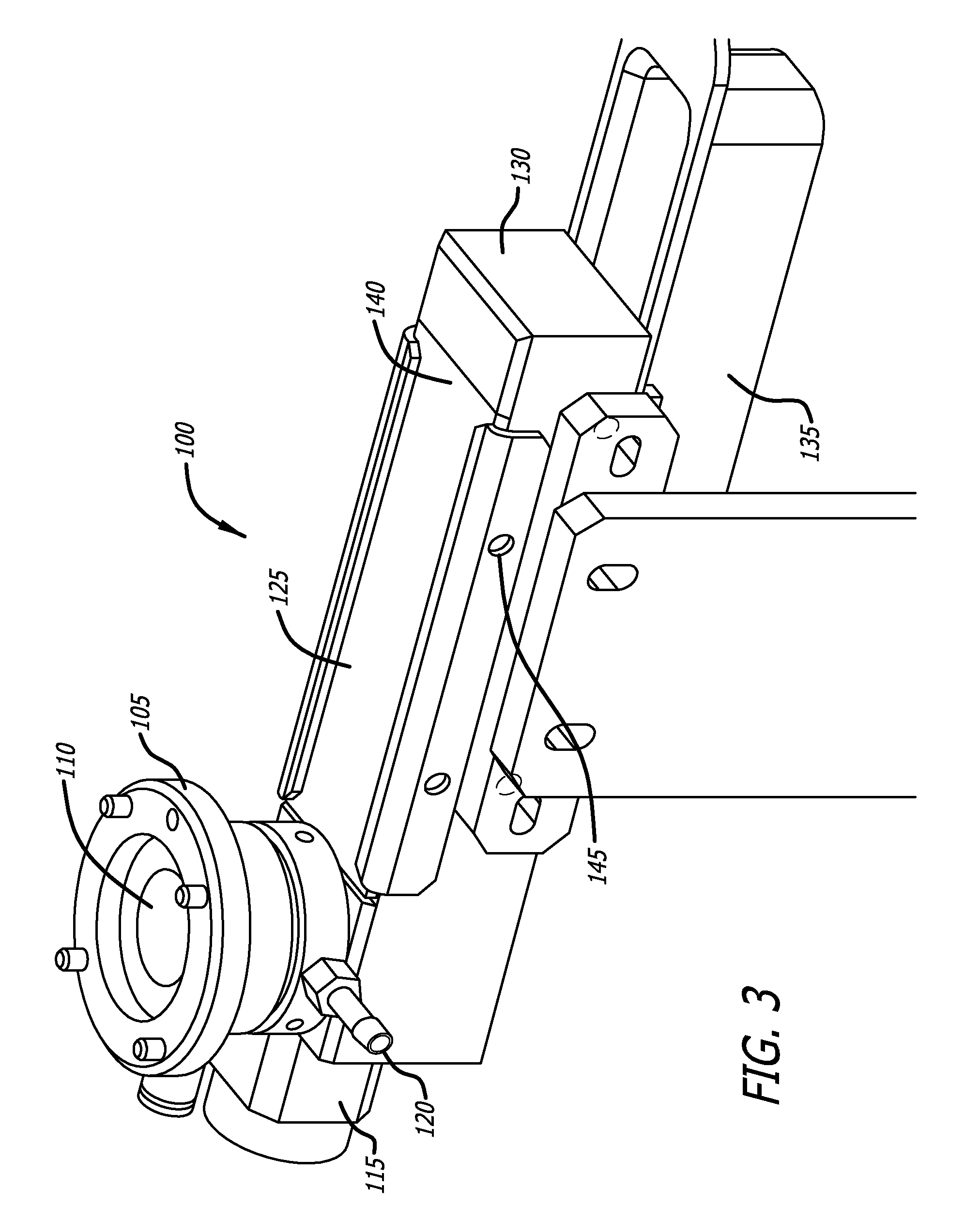
[0029]In still another aspect, the present invention includes a cutting mandrel that provides for flow of a shielding gas and also provides a means for dispersing, scattering, or diffusing a laser beam before it can produce unwanted damage to a section of tubing. The various aspects of the cutting mandrel above are advantageous in that they provide for diffraction or dispersion of a laser beam that prevents the beam from melting or otherwise damaging the inner surface of tubing used to form a stent.
[0030]In another aspect, channels formed within the cutting mandrel allow for the introduction of a shield gas within the inner diameter of a length of tubing used to form a stent and may reduce material embrittlement, material oxidation, or other undesired effects due to stent material heating and / or exposure to certain gases. In other aspects, introduction of a shielding gas may also be used to assist in maintaining the optical clarity of the dispersion element and keep the channels clean and free from particulate and other matter that is generated during the laser cutting process.
[0031]In still another aspect, a close fit between the cutting mandrel and the inner wall of the tube being cut into a stent may compensate for a lack of tube straightness and thus improve laser cutting efficiency and stent strut dimensional control.

Problems solved by technology

Although the stents are effective in opening the stenotic lumen, the foreign material and structure of the stents themselves may exacerbate the occurrence of restenosis or thrombosis.
Although PTCA and related procedures aid in alleviating intraluminal constrictions, such constrictions or blockages reoccur in many cases.
One process that is particularly susceptible to these affects is the laser cutting process, since it introduces both heat in the form of laser energy and foreign materials in the form of shielding gases and surrounding environmental gases into the stent cutting process.
Oxygen is a particular concern because it can lead to material oxidation and embrittlement of the material due to reactions between the oxygen and the tubing material in the presence of the heat generated by the laser-cutting beam.
Under certain conditions, such as when the shielding gas is flowing at a low rate, or when the shielding gas nozzle is wide enough to allow entry of particulates, the laser optics can become marred by the escaping particulates.
The particulates may deposit on the lens of the laser equipment and over time, these depositions can obscure the path of the laser beam creating detrimental changes the laser beam characteristics.
For example, the beam may lose focus, which can result in a less clean cut or longer cutting times. Another concern is the debris from laser cutting may be accumulated inside the cutting kerf, thereby reducing the cutting efficiency of the laser beam.
Another problem with using a laser to cut a stent pattern into a tube is that to ensure that a laser will cut the tubing used to form stents, there must be appropriate laser power to melt or ablate the tubing material.
However, when the laser cuts through the tubing, the laser beam may propagate beyond the tubing wall and may melt or burn the opposing wall of the tubing material.
This may cause defects in the stent pattern which is ultimately cut from the opposing wall of the tubing.

Method used


Image

  • Laser cutting system
  • Laser cutting system
  • Laser cutting system

Examples


Embodiment Construction

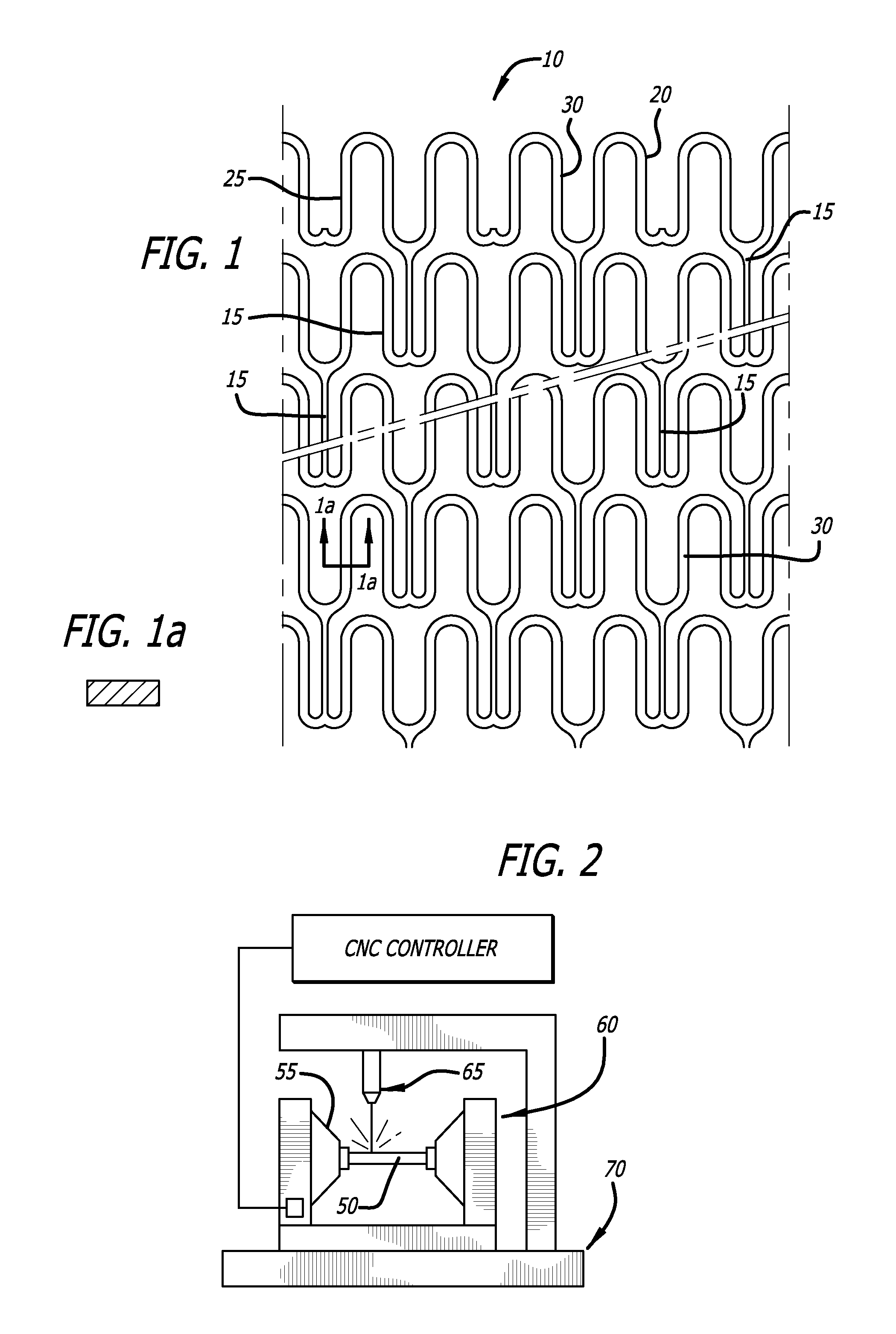
[0054]FIG. 1 is an enlarged perspective view of a stent 10 illustrating an exemplary stent pattern and showing the placement of interconnecting elements 15 between adjacent radially expandable cylindrical elements. Each pair of the interconnecting elements 15 on one side of a cylindrical element are preferably placed to achieve maximum flexibility for a stent. In the embodiment shown in FIG. 1, the stent 10 has three interconnecting elements 15 between adjacent radially expandable cylindrical elements which are 120 degrees apart. Each pair of interconnecting elements 15 on one side of a cylindrical element are offset radially 60 degrees from the pair on the other side of the cylindrical element. The alternation of the interconnecting elements results in a stent which is longitudinally flexible in essentially all directions. Various configurations for the placement of interconnecting elements are possible. However, as previously mentioned, all of the interconnecting elements of an in...


PUM

PropertyMeasurementUnit
outer diameteraaaaaaaaaa
thicknessaaaaaaaaaa

Abstract

A laser cutting system including a chamber configured to provide a controlled environment while the laser is being used to cut a pattern into a material to reduce or eliminate heat and oxygen related changes to the mechanical characteristics of the material. A system for providing a gas to the controlled environment within the chamber, as well as a means for exhausting gas and cutting debris from the chamber is also described. A cutting mandrel that provides for flow of a shielding gas and also provides a means for dispersing a laser beam before it can produce unwanted damage to a section of tubing is also described.

Description

CROSS-REFERENCES TO RELATED APPLICATIONS[0001]This application claims priority from U.S. Provisional Application No. 61 / 149,655, filed Feb. 3, 2009 and U.S. Provisional Application No. 61 / 149,660, filed Feb. 3, 2009 incorporated by reference in its entirety.[0002]This application is also related to U.S. application Ser. No. ______ entitled IMPROVED LASER CUTTING PROCESS FOR FORMING STENTS, filed Feb. 3, 2010, and U.S. application Ser. No. ______ entitled MULTIPLE BEAM LASER SYSTEM FOR FORMING STENTS, filed Feb. 3, 2010.BACKGROUND[0003]1. Field of the Invention[0004]The present invention relates generally to implantable medical devices and to a method for manufacturing implantable medical devices. These implantable medical devices may also be capable of retaining therapeutic materials and dispensing the therapeutic materials to a desired location of a patient's body. More particularly, the present invention relates to a method for forming the structure of a stent or intravascular or ...

Claims


Application Information

Patent Timeline
Patent Type & Authority Applications(United States)
IPC IPC(8): B23K26/00
CPCB23K26/38
Inventor OW, RODNEY C.WEBLER, WILLIAM E.VON OEPEN, RANDOLF
Owner ABBOTT CARDIOVASCULAR
Why Eureka
Try Eureka