Display device, touch sensor, and method for manufacturing display device
a display device and touch sensor technology, applied in the field of display devices, touch sensors, and methods for manufacturing display devices, can solve the problems of reducing the reliability of devices, occurrence of trouble, and reducing the thickness of display panels, so as to prevent the deformation of elastic members in response to external pressure from the upper side of the electrode, the effect of enhancing image quality and preventing the deformation of elastic members
Inactive Publication Date: 2010-08-05
JAPAN DISPLAY WEST
View PDF6 Cites 19 Cited by
- Summary
- Abstract
- Description
- Claims
- Application Information
AI Technical Summary
Benefits of technology
[0012]In the above-described display device, reduction in the thickness of the display panel increases the possibility of the breaking of a component such as the electrode due to external pressure, and possibly lowers the device reliability.
[0018]It may be effective to increase the area of the surface of the protruding elastic member on which the touch electrode is provided in order to avoid the trouble. However, in this case, the aperture ratio of the liquid crystal panel is lowered and thus the quality of displayed images is possibly lowered.
[0021]There is a need to provide a display device, a touch sensor, and a method for manufacturing a display device, each capable of realizing enhancement in the image quality and enhancement in the device reliability.
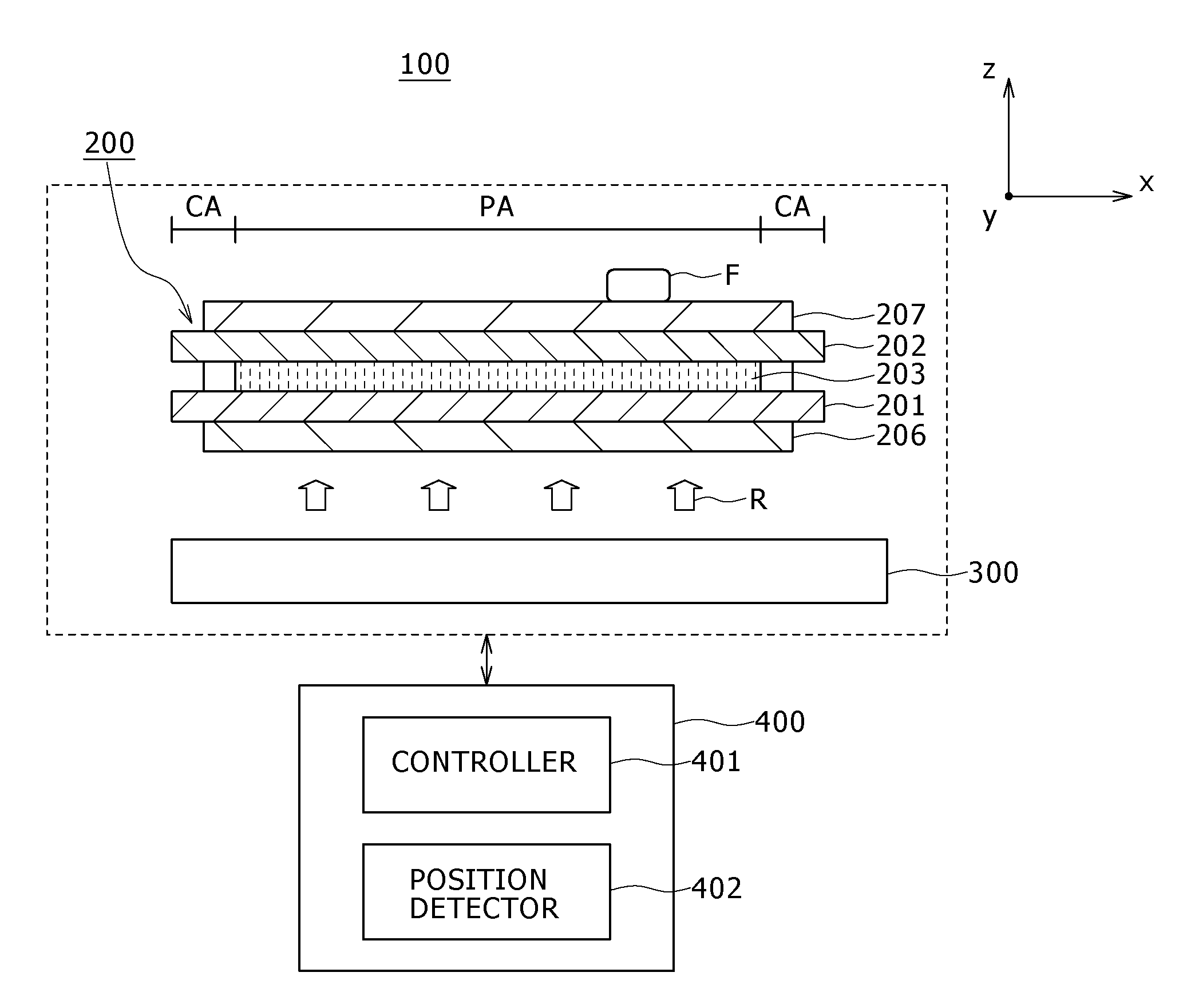
[0026]In the embodiments of the present invention, the protruding elastic member is formed over the substrate. This elastic member is so formed that the plurality of steps are provided in the direction perpendicular to the surface of the substrate. Specifically, the elastic member is so formed as to include a first step formed with a first height as the largest height and a second step formed with a second height lower than the first height. Furthermore, the electrode is formed on the elastic member. This electrode is so provided on the elastic member as to cover the surface of the plurality of steps of the elastic member. Specifically, the electrode is so provided on the elastic member as to include the part covering the surface of the first step and the second step of the elastic member. Therefore, large deformation of the elastic member in response to application of external pressure from the upper side of the electrode can be prevented. Thus, the breaking of the electrode can be prevented.
[0027]The embodiments of the present invention can provide a display device, a touch sensor, and a method for manufacturing a display device, each capable of realizing enhancement in the image quality and enhancement in the device reliability.
Problems solved by technology
In the above-described display device, reduction in the thickness of the display panel increases the possibility of the breaking of a component such as the electrode due to external pressure, and possibly lowers the device reliability.
The occurrence of this trouble possibly emerges particularly if the touch electrode composed of a rigid material is provided on the protruding elastic member in the liquid crystal panel having the built-in touch sensors.
For example, possibly the breaking of the touch electrode occurs and the touch panel function is spoiled.
Method used
View moreImage
Smart ImageViewing Examples
Examples
first embodiment (
1. First Embodiment (the position of the lower step of the elastic member is at an end in top view)
second embodiment (
2. Second Embodiment (the position of the lower step of the elastic member is at the center in top view)
third embodiment (
3. Third Embodiment (the planar shape of the lower step of the elastic member is a triangle)
Login to View More PUM
 Abstract
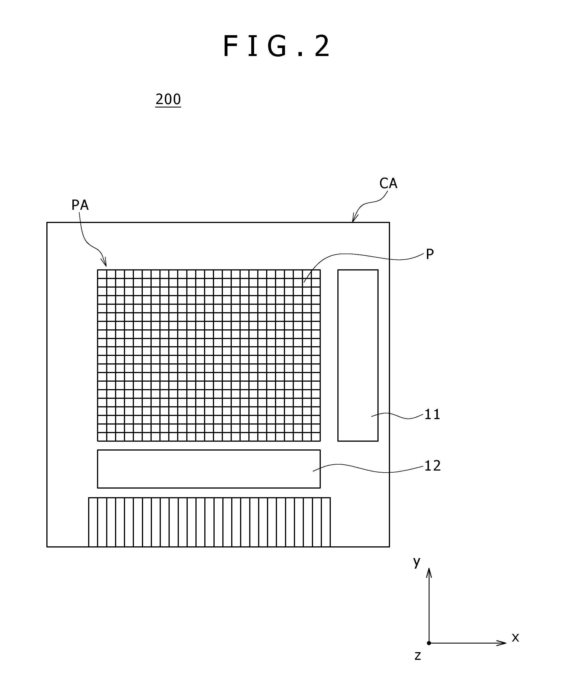
Disclosed herein is a display device including: a display panel configured to display an image in a display area and have a substrate over which a protruding elastic member and an electrode provided on the elastic member are formed in the display area; wherein a plurality of steps are provided in the elastic member in a direction perpendicular to a surface of the substrate, and the electrode is so provided on the elastic member as to include part covering a surface of the plurality of steps.
Description
BACKGROUND OF THE INVENTION[0001]1. Field of the Invention[0002]The present invention relates to display devices, touch sensors, and methods for manufacturing a display device, and particularly to a display device, a touch sensor, and a method for manufacturing a display device in each of which a protruding elastic member is formed and an electrode is formed on this elastic member.[0003]2. Description of the Related Art[0004]Display devices such as liquid crystal display devices and organic EL display devices have advantages such as small thickness, light weight, and low power consumption.[0005]As one of such display devices, the liquid crystal display device has a liquid crystal panel obtained by enclosing a liquid crystal layer between a pair of substrates as a display panel. The liquid crystal panel is e.g. a transmissive panel. Specifically, illuminating light emitted from an illuminating device such as a backlight provided on the back side of the liquid crystal panel is modulat...
Claims
Login to View More Application Information
Patent Timeline
 IPC IPC(8): G06F3/041
CPCG02F1/133371G02F1/13338G06F3/045G02F1/1343G06F3/0412G02F1/133555
Inventor KOITO, TAKEOTAMAKI, MASAYA
Owner JAPAN DISPLAY WEST
Features
- R&D
- Intellectual Property
- Life Sciences
- Materials
- Tech Scout
- Unparalleled Data Quality
- Higher Quality Content
- 60% Fewer Hallucinations
Learn More Browse by: Latest US Patents, China's latest patents, Technical Efficacy Thesaurus, Application Domain, Technology Topic, Popular Technical Reports.
© 2025 PatSnap. All rights reserved.Legal|Privacy policy|Modern Slavery Act Transparency Statement|Sitemap|About US| Contact US: help@patsnap.com


