Liquid crystal display device

a liquid crystal display and display device technology, applied in non-linear optics, instruments, optics, etc., to achieve the effect of increasing the contrast ratio

Active Publication Date: 2010-08-05
SEMICON ENERGY LAB CO LTD
View PDF13 Cites 59 Cited by
  • Summary
  • Abstract
  • Description
  • Claims
  • Application Information

AI Technical Summary

Benefits of technology

[0013]Therefore, liquid crystal molecules in the entire liquid crystal layer, which also includes the liquid crystal molecules in a thickness direction, can be made to respond and white transmittance can be improved. Accordingly, the contrast ratio which is a ratio of white transmittance to black transmittance (light transmittance in black display) can also be increased.
[0017]A blue phase liquid crystal material is used for a liquid crystal layer. The blue phase liquid crystal material has a short response time of 1 msec or less and is capable of high-speed response. Thus, a high performance liquid crystal display device can be achieved.
[0022]A cholesteric blue phase and a smectic blue phase, which are blue phases, are found in a liquid crystal material having a cholesteric phase or a smectic phase with a relatively short helical pitch of 500 nm or less. The alignment of the liquid crystal material has a double twist structure. Having the order of less than or equal to a wavelength of visible light, the liquid crystal material is transparent, and optical modulation action is generated through a change in alignment order by voltage application. A blue phase is optically isotropic and thus has no viewing angle dependence. Thus, an alignment film is not necessarily formed; therefore, display image quality can be improved and cost can be reduced.
[0023]The blue phase is exhibited only within a narrow temperature range; therefore, it is preferable that a photocurable resin and a photopolymerization initiator be added to a liquid crystal material and polymer stabilization treatment be conducted in order to expand the temperature range. The polymer stabilization treatment is conducted in such a manner that a liquid crystal material including a liquid crystal, a chiral agent, a photocurable resin, and a photopolymerization initiator is irradiated with light having a wavelength with which the photocurable resin and the photopolymerization initiator are reacted. Such polymer stabilization treatment may be conducted by light irradiation of a liquid crystal material exhibiting an isotropic phase or by light irradiation of a liquid crystal material exhibiting a blue phase under the control of the temperature. For example, the polymer stabilization treatment is conducted in such a manner that the temperature of a liquid crystal layer is controlled and the liquid crystal layer is irradiated with light with a blue phase exhibited. Note that the polymer stabilization treatment is not limited to this manner and may be performed in such a manner that a liquid crystal layer is irradiated with light with an isotropic phase exhibited at a temperature within +10° C., preferably +5° C. from the phase transition temperature between the blue phase and the isotropic phase. The phase transition temperature between a blue phase and an isotropic phase refers to a temperature in transition from a blue phase to an isotropic phase when temperature is raised or a temperature in transition from an isotropic phase to a blue phase when temperature is reduced. As an example of the polymer stabilization treatment, the following method can be employed: after heating a liquid crystal layer to exhibit an isotropic phase, the temperature of a liquid crystal layer is gradually reduced so that the phase changes to a blue phase, and then, irradiation with light is conducted while the temperature at which a blue phase is exhibited is kept. Alternatively, after the phase changes to an isotropic phase by gradually heating a liquid crystal layer, the liquid crystal layer can be irradiated with light at a temperature within +10° C., preferably +5° C. from the phase transition temperature between the blue phase and the isotropic phase (with an isotropic phase exhibited). Moreover, in the case where an ultraviolet curable resin (a UV curable resin) is used as the photocurable resin included in the liquid crystal material, the liquid crystal layer may be irradiated with ultraviolet rays. Even in the case where a blue phase is not exhibited, if polymer stabilization treatment is conducted by irradiation with light at a temperature within +10° C., preferably +5° C. from the phase transition temperature between the blue phase and the isotropic phase (with an isotropic phase exhibited), the response time can be made as short as 1 msec or less and thus high-speed response is possible.
[0030]In a liquid crystal display device using a blue phase liquid crystal layer, a contrast ratio can be increased.

Problems solved by technology

A problem for liquid crystal display devices is that high white transmittance (the ratio of light transmittance in white display) is necessary in order to achieve a high contrast.

Method used


Image

  • Liquid crystal display device
  • Liquid crystal display device
  • Liquid crystal display device

Examples


embodiment 1

[0057]A liquid crystal display device is described with reference to FIGS. 1A to 1C,

[0058]FIGS. 19A and 19B, FIGS. 20A and 20B, FIGS. 21A and 21B, FIGS. 22A and 22B, and FIGS. 23A and 23B.

[0059]FIGS. 1A to 1C are cross-sectional views of liquid crystal display devices.

[0060]FIG. 1A illustrates a liquid crystal display device in which a first substrate 200 and a second substrate 201 are positioned to face each other with a liquid crystal layer 208 which uses a blue phase liquid crystal material sandwiched therebetween. First structure bodies 233a and 233b, pixel electrode layers 230a and 230b, and second common electrode layers 232a, 232b, and 232c are provided between the first substrate 200 and the liquid crystal layer 208. First common electrode layers 231a, 231b, and 231c are provided between the second substrate 201 and the liquid crystal layer 208. The first structure bodies 233a and 233b are provided so as to project into the liquid crystal layer 208 from a surface of the firs...

embodiment 2

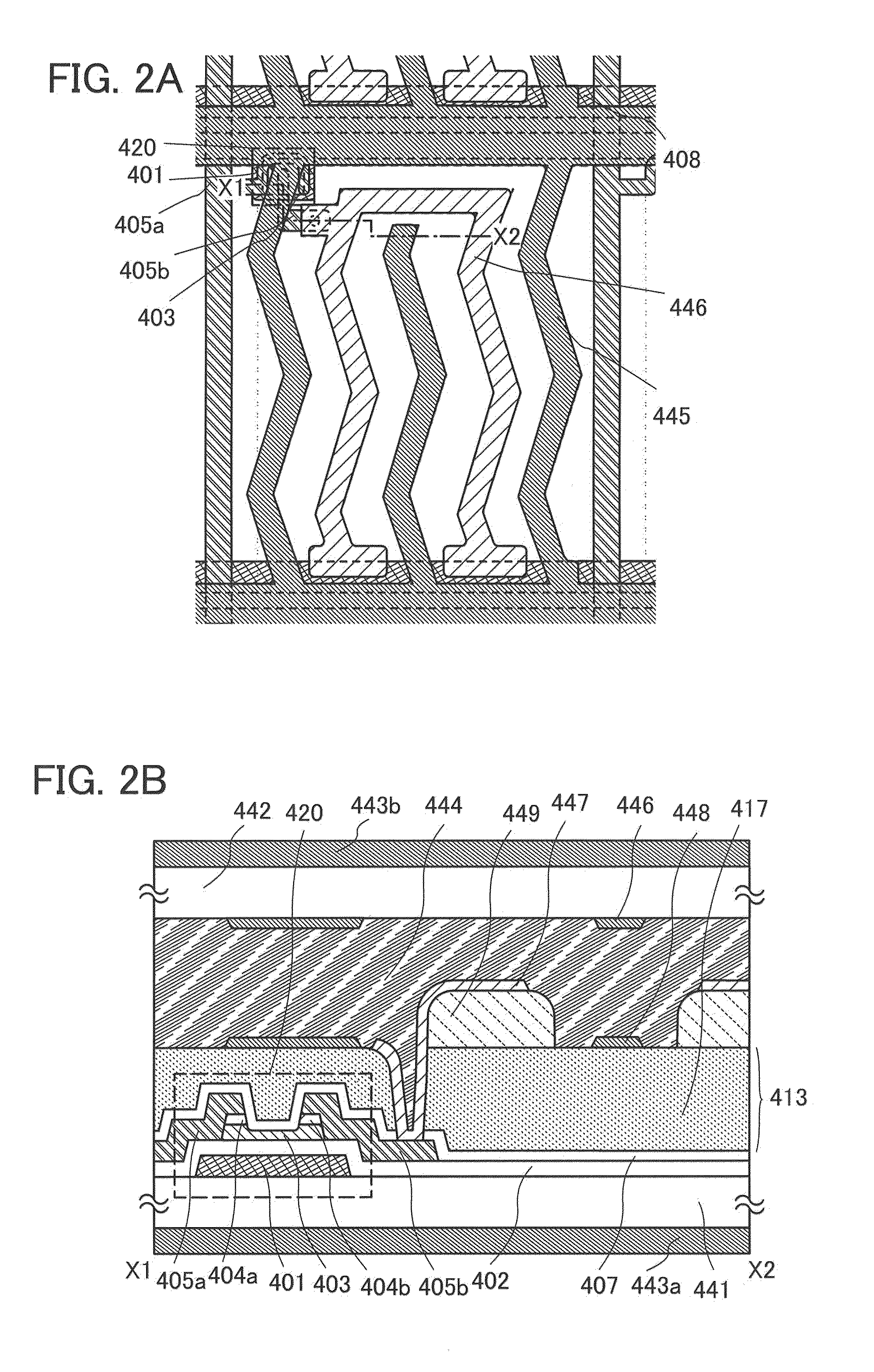
[0095]The invention disclosed in this specification is applicable to either a passive matrix liquid crystal display device or an active matrix liquid crystal display device. An example of the active matrix liquid crystal display device is described with reference to FIGS. 2A and 2B, FIGS. 8A to 8D, and FIGS. 18A and 18B.

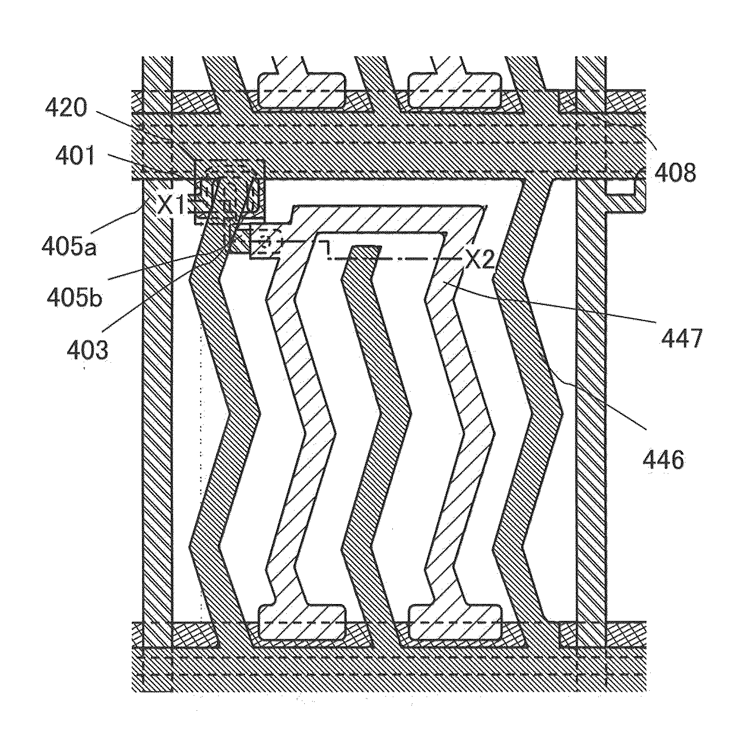
[0096]FIG. 2A is a plan view of a liquid crystal display device and illustrates one pixel. FIG. 2B is a cross-sectional view taken along the line X1-X2 in FIG. 2A.

[0097]In FIG. 2A, a plurality of source wiring layers (including a wiring layer 405a) is provided in parallel to each other (extended in a vertical direction in the drawing) and apart from each other. A plurality of gate wiring layers (including a gate electrode layer 401) is extended in a direction generally perpendicular to the source wiring layers (a horizontal direction in the drawing) and provided apart from each other. Capacitor wiring layers 408 are adjacent to the plurality of gate wiring layers and...

embodiment 3

[0156]FIGS. 4A and 4B illustrate an example in which a color filter is provided on an outer side of substrates between which a liquid crystal layer is sandwiched in Embodiment 2. Note that components in common with those in Embodiments 1 and 2 can be formed using a similar material and manufacturing method, and detailed description of the same portions and portions having similar functions is omitted.

[0157]FIG. 4A is a plan view of a liquid crystal display device and illustrates one pixel. FIG. 4B is a cross-sectional view taken along the line X1-X2 in FIG. 4A.

[0158]In the plan view of FIG. 4A, in a manner similar to Embodiment 2, a plurality of source wiring layers (including the wiring layer 405a) is provided in parallel to each other (extended in a vertical direction in the drawing) and apart from each other. A plurality of gate wiring layers (including the gate electrode layer 401) is provided apart from each other and extended in a direction generally perpendicular to the sourc...


PUM

PropertyMeasurementUnit
response timeaaaaaaaaaa
phase transition temperatureaaaaaaaaaa
temperatureaaaaaaaaaa

Abstract

In a liquid crystal display device including a blue phase liquid crystal layer, first and second common electrode layers, which are positioned to face each other, sandwich the blue phase liquid crystal layer therebetween and have opening patterns (slits), and a pixel electrode layer has an opening pattern. The pixel electrode layer is formed over a structure body which projects into the liquid crystal layer from a surface of a first substrate on a liquid crystal layer side, and the pixel electrode layer is positioned between the first and second common electrode layers in the liquid crystal layer. Electric fields are applied between the pixel electrode layer and the first and second common electrode layers, so that the electric fields are formed in the entire liquid crystal layer and liquid crystal molecules can be controlled by using the electric fields.

Description

BACKGROUND OF THE INVENTION[0001]1. Field of the Invention[0002]The present invention relates to a liquid crystal display device and a method for manufacturing the liquid crystal display device.[0003]2. Description of the Related Art[0004]A liquid crystal display device having a liquid crystal element, a light emitting device having a self-light emitting element, a field emission display (FED), and the like has competed and developed in the market of display devices which are very thin and lightweight (so-called flat panel displays).[0005]The increase in the response speed of liquid crystal molecules is required for liquid crystal display devices. A display mode of a liquid crystal has a variety of types, and among them, a ferroelectric liquid crystal (FLC) mode, an optical compensated birefringence (OCB) mode, and a mode using a blue phase liquid crystal can be given as a liquid crystal mode capable of high-speed.[0006]In particular, with the use of a mode using a blue phase liquid...

Claims


Application Information

Patent Timeline
Patent Type & Authority Applications(United States)
IPC IPC(8): G02F1/1343G02F1/1335G02F1/1333
CPCG02F1/134363G02F2001/13793G02F2001/134381G02F1/134381G02F1/13793G02F1/133512G02F1/136209G02F1/136227G02F1/136286G02F1/13718G02F1/134318
Inventor KUBOTA, DAISUKEISHITANI, TETSUJIYAMASHITA, AKIO
Owner SEMICON ENERGY LAB CO LTD
Why Eureka
Try Eureka