Three-dimensional shape measuring apparatus, three-dimensional shape measuring method, three-dimensional shape measuring program, and recording medium

a three-dimensional shape and measuring method technology, applied in the direction of measurement devices, instruments, image analysis, etc., can solve the problems of long image taking time, difficulty in arranging the line sensor, and long imaging time, and achieve the effect of quick and easy manner

Inactive Publication Date: 2010-08-05
ORMON CORP
View PDF2 Cites 51 Cited by
  • Summary
  • Abstract
  • Description
  • Claims
  • Application Information

AI Technical Summary

Benefits of technology

[0012]One or more embodiments of the present invention provides a three-dimensional shape measuring apparatus and a three-dimensional shape measuring method capable of measuring three-dimensional shape information of a target object over a wide visual field in a swift and easy manner.
[0015]According to the above configuration, the three-dimensional shape measuring apparatus is arranged with a first line sensor for reading the optical pattern projected onto the target object as an image and a second line sensor for reading an image of the target object onto which the optical pattern is not projected. In this way, the imaging region can be extended in the longitudinal direction (the sub-scan direction) of the line sensor by using the line sensor instead of the area sensor. Therefore, the target object can be imaged at a high resolution while reducing the number of times the target object is moved relatively in the sub-scan direction with respect to the line sensor (preferably, the number of times the target object is moved is reduced to zero), which enables measuring the three-dimensional shape information in a swift and precise manner.
[0024]However, in the three-dimensional shape measuring apparatus according to one or more embodiments of the present invention, the optical pattern-emitted region and the optical pattern-non-emitted region are arranged so as not to overlap with each other, and the first line sensor and the second line sensor are arranged so that the first line sensor and the second line sensor can image the above regions at a time. In the above configuration, it is not necessary to image the entire measurement region by moving the target object multiple times during calculation of an image obtained by removing background information from the image taken by the first and second line sensors. Therefore, the three-dimensional shape measuring apparatus according to one or more embodiments of the present invention achieves the effect of being able to take the required image with only one shot.
[0025]Therefore, it takes less time to take the image, it is not necessary to arrange a mechanism such as a half mirror for switching between emission and non-emission of the optical pattern, it is not necessary to arrange a linear scaler in order to correctly adjust the position when imaging is performed multiple times, and it is possible to reduce the cost and achieve a faster imaging rate.
[0027]According to the above configuration, the three-dimensional shape measuring method can be provided that achieves the same effect as the above-described three-dimensional shape measuring apparatus.

Problems solved by technology

However, when the area sensor is used, because the target object does not fit into one imaging visual field, it is necessary that the area sensor be moved in both a lengthwise direction and a crosswise direction to take the one imaging visual field while the one imaging visual field is divided into plural portions, which results in the imaging time being lengthened.
In the conventional techniques, however, there is difficulty in arranging the line sensor or it takes a long time to take the image.
However, it is actually difficult for the four line sensors to be arranged as described above.
Thus, in the technique described in Patent Document 1, arrangement of the line sensor becomes difficult.
In addition, because the plural line sensors are required, upsizing, price increase, and the increased frequency of troubles might arise in the measuring apparatus.
Therefore, in this case, it is also necessary that the two line sensors be correctly arranged, which results in the arrangement of the line sensor becoming difficult.
Furthermore, since the method of the Patent Document 2 uses the stereo method, it is difficult to improve the measurement precision of the three-dimensional shape to a resolution not more than a pixel of the line sensor.

Method used


Image

  • Three-dimensional shape measuring apparatus, three-dimensional shape measuring method, three-dimensional shape measuring program, and recording medium
  • Three-dimensional shape measuring apparatus, three-dimensional shape measuring method, three-dimensional shape measuring program, and recording medium
  • Three-dimensional shape measuring apparatus, three-dimensional shape measuring method, three-dimensional shape measuring program, and recording medium

Examples


first embodiment

[0070]Embodiments of the present invention will be described below with reference to FIGS. 1 to 11. In embodiments of the invention, numerous specific details are set forth in order to provide a more thorough understanding of the invention. However, it will be apparent to one of ordinary skill in the art that the invention may be practiced without these specific details. In other instances, well-known features have not been described in detail to avoid obscuring the invention.

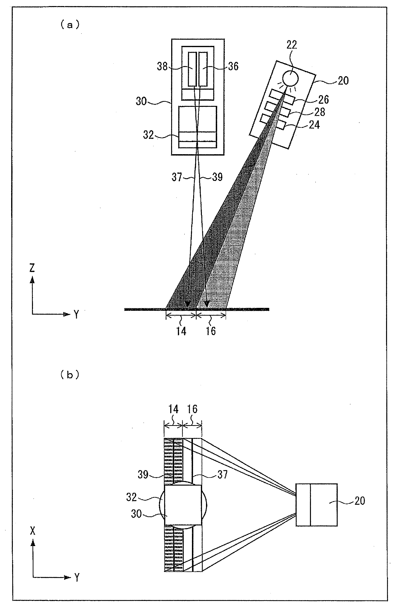
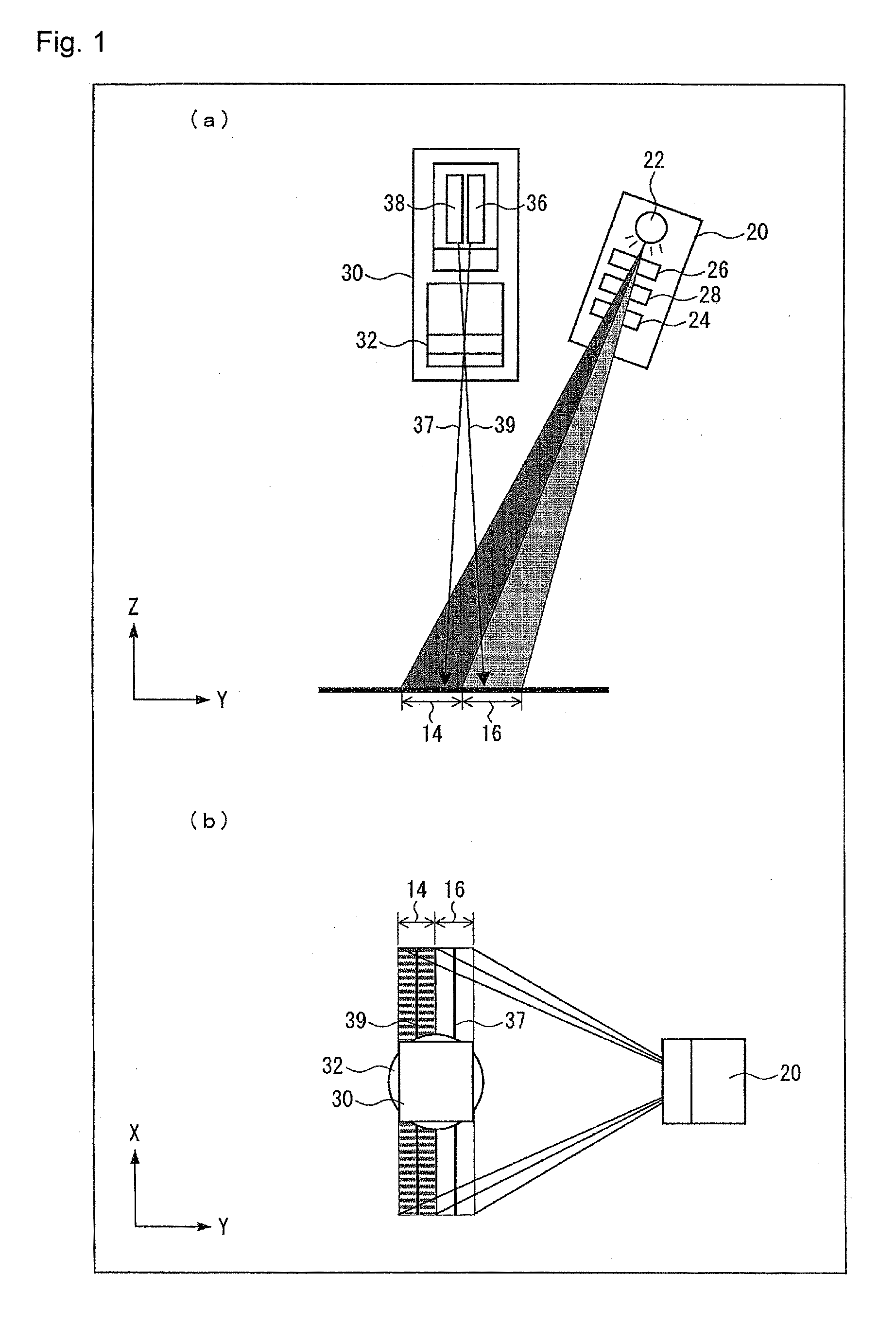
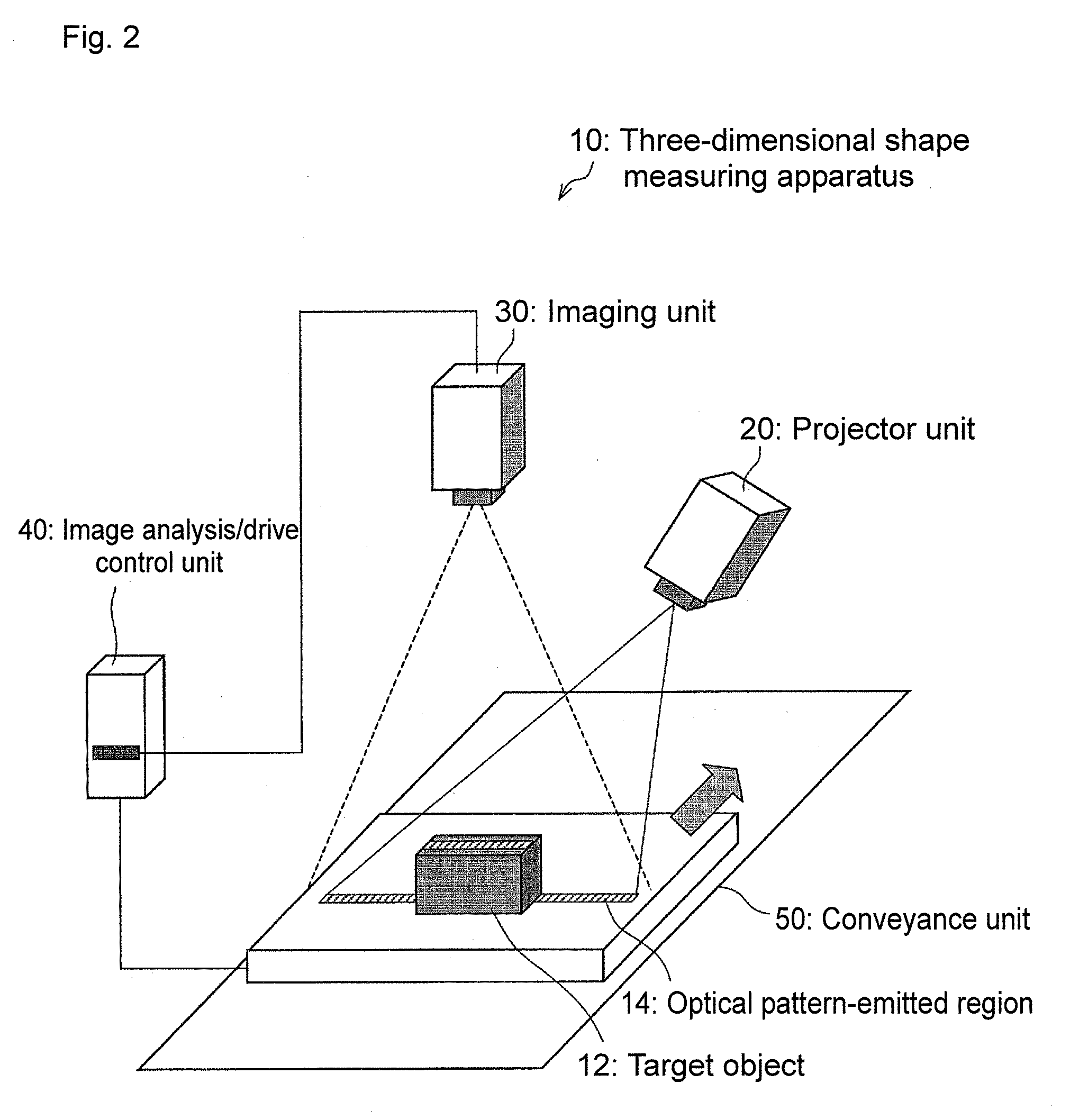
[0071]FIG. 1 is a view showing a schematic configuration of a three-dimensional shape measuring apparatus 10 according to the present embodiment. FIG. 1(a) is a cross sectional view and FIG. 1(b) is a top view. FIG. 2 is a conceptual view showing a physical structure of the three-dimensional shape measuring apparatus 10. FIG. 3 is a functional block diagram showing a configuration of an essential portion of the three-dimensional shape measuring apparatus 10. As shown in FIG. 1 to FIG. 3, the three-dimensional s...

second embodiment

[0152]Subsequently, another embodiment of the present invention will be hereinafter described with reference to FIG. 12 and FIG. 13. The three-dimensional shape measuring apparatus 10 according to the present embodiment is different from the three-dimensional shape measuring apparatus 10 shown in FIG. 1 in the configuration of the line camera of the imaging unit 30, but the other structures are the same. The elements having the same functions as the elements described in the above embodiment are denoted with the same reference numerals, and the description thereabout is omitted.

[0153]FIG. 12 is a view for illustrating the arrangement of line sensors arranged on a color imaging camera (color imaging means) used in the three-dimensional shape measuring apparatus 10 according to the present embodiment. The line sensors detect brightness of colors of red, green, blue, black and white. In FIG. 12, KLI-4104 (CSL8000CL) made by Kodak Company is shown as an example of a color sensor includi...

third embodiment

[0163]Subsequently, still another embodiment of the present invention will be hereinafter described with reference to FIG. 14. FIG. 14 is a view showing a schematic structure of the three-dimensional shape measuring apparatus 10 according to the present embodiment. The elements having the same functions as the elements described in the above embodiments are denoted with the same reference numerals, and the description thereabout is omitted.

[0164]The three-dimensional shape measuring apparatus 10 of FIG. 14 is different from the above-described embodiments in that the first line sensor 36 and the second line sensor 38 are respectively arranged on cameras each having a single line sensor and that mirrors 34 are arranged so as to direct the optical axes of the line sensors of the cameras toward the measurement surface, but the other structures are the same.

[0165]In FIG. 14, a first camera having the first line sensor 36 and a second camera having the second line sensor 38 are arranged ...


PUM


Abstract

An apparatus for measuring a three-dimensional shape of a target object by analyzing an optical pattern projected onto the target object has an optical pattern projecting device that projects the optical pattern onto a portion of a measurement surface on which the target object is placed, the optical pattern having brightness changing periodically according to a position, a first line sensor that images an optical pattern-emitted region onto which the optical pattern is projected, a second line sensor that images an optical pattern-non-emitted region onto which the optical pattern is not projected, and a processing device that calculates a phase of the optical pattern at a pixel included in an image obtained by removing background information from images taken by the first and second line sensors based on a brightness value of the pixel and a neighboring pixel in the image, and calculates height information based on the calculated phase.

Description

TECHNICAL FIELD[0001]The present invention relates to a three-dimensional shape measuring apparatus, a three-dimensional shape measuring method, a three-dimensional shape measuring program, and recording medium which measures a three-dimensional shape of a target object by analyzing an optical pattern projected onto the target object.BACKGROUND ART[0002]An example of means for obtaining three-dimensional shape information on an object by image analysis includes a method of analyzing a deformation amount of an optical pattern changed according to a three-dimensional shape of a target object by projecting the optical pattern onto the target object existing in a predetermined imaging visual field. A light-section method, a spatial encoding method, a fringe analysis method can be cited as typical examples. These methods are based on the principle of triangulation. Among others, for the fringe analysis method, there are proposed many techniques such as spatial fringe analysis and tempora...

Claims


Application Information

Patent Timeline
Patent Type & Authority Applications(United States)
IPC IPC(8): G01B11/24G01B11/245G01B11/255G06T1/00
CPCG01B11/245G06T7/0057G01B11/2513G01B11/2509G06T7/521
Inventor MITSUMOTO, DAISUKEHONMA, YUKI
Owner ORMON CORP
Why Eureka
Try Eureka