System and Method of Focusing Electromagnetic Radiation

a technology of electromagnetic radiation and system, applied in the field of focusing electromagnetic radiation, can solve the problems of complexity, cost, stability and reliability of a prior art 2, and achieve the effects of reducing complexity, simplifying assembly and calibration of the system, and reducing the number of parts

Active Publication Date: 2010-08-05
GREEN STEVEN RUSSELL
View PDF15 Cites 15 Cited by
  • Summary
  • Abstract
  • Description
  • Claims
  • Application Information

AI Technical Summary

Benefits of technology

[0018]Much of the complexity, cost, stability and reliability of a prior art 2-axis planar tracking system is proportional to the part count of the mirror carrier assembly. The system of the present invention has a part count that is reduced and the assembly and calibration of the system is simplified. In one embodiment, this invention reduces complexity in relation to the 2-axis rotational motion systems by replacing 2-axis motion with translational motion. Translational motion is the movement of an object through space without rotation or tilt. The use of translational movement reduces mirror mount complexity, the number of required components, and simplifies the assembly process.
[0019]Further, a mirror angle calibration method for m...

Problems solved by technology

Much of the complexity, cost, stability and reliability of a prior art 2-axis pl...

Method used


Image

  • System and Method of Focusing Electromagnetic Radiation
  • System and Method of Focusing Electromagnetic Radiation
  • System and Method of Focusing Electromagnetic Radiation

Examples


Embodiment Construction

[0042]While this invention is susceptible of embodiment in many different forms, there are shown in the drawings and will be described herein in detail specific embodiments thereof with the understanding that the present disclosure is to be considered as an exemplification of the principles of the invention and is not intended to limit the invention to the specific embodiments illustrated.

Solar Tracking System Overview

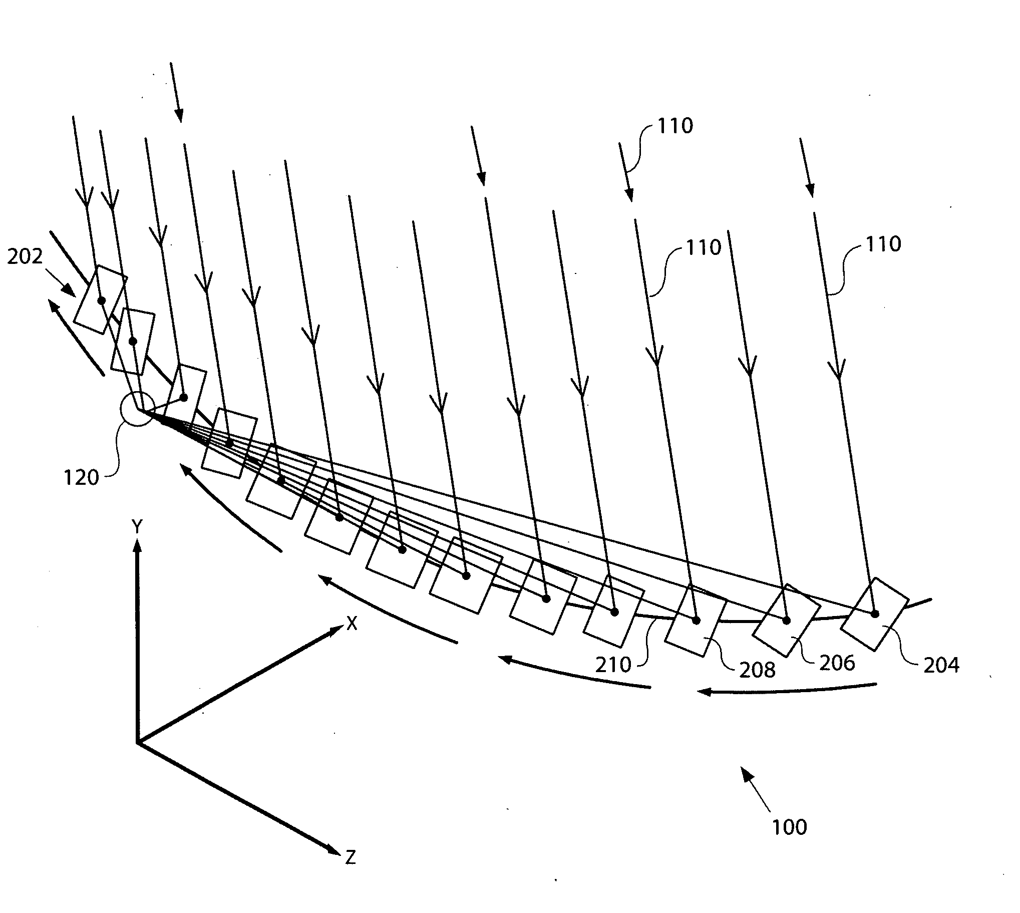
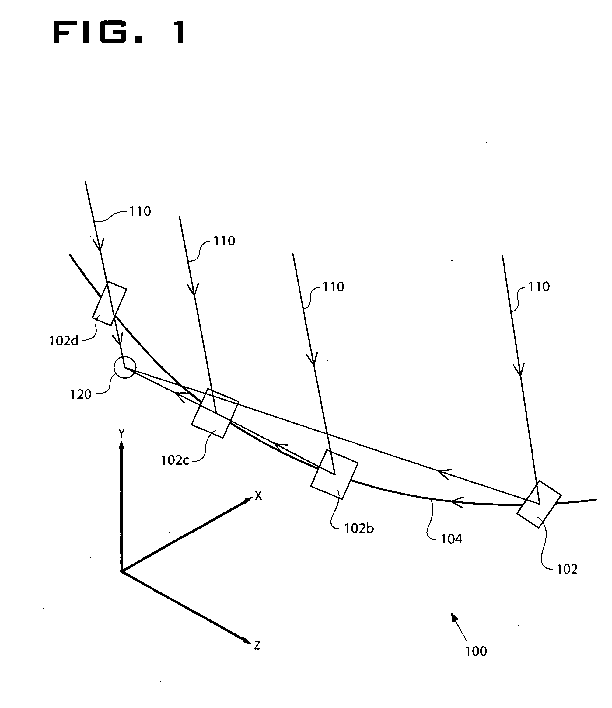
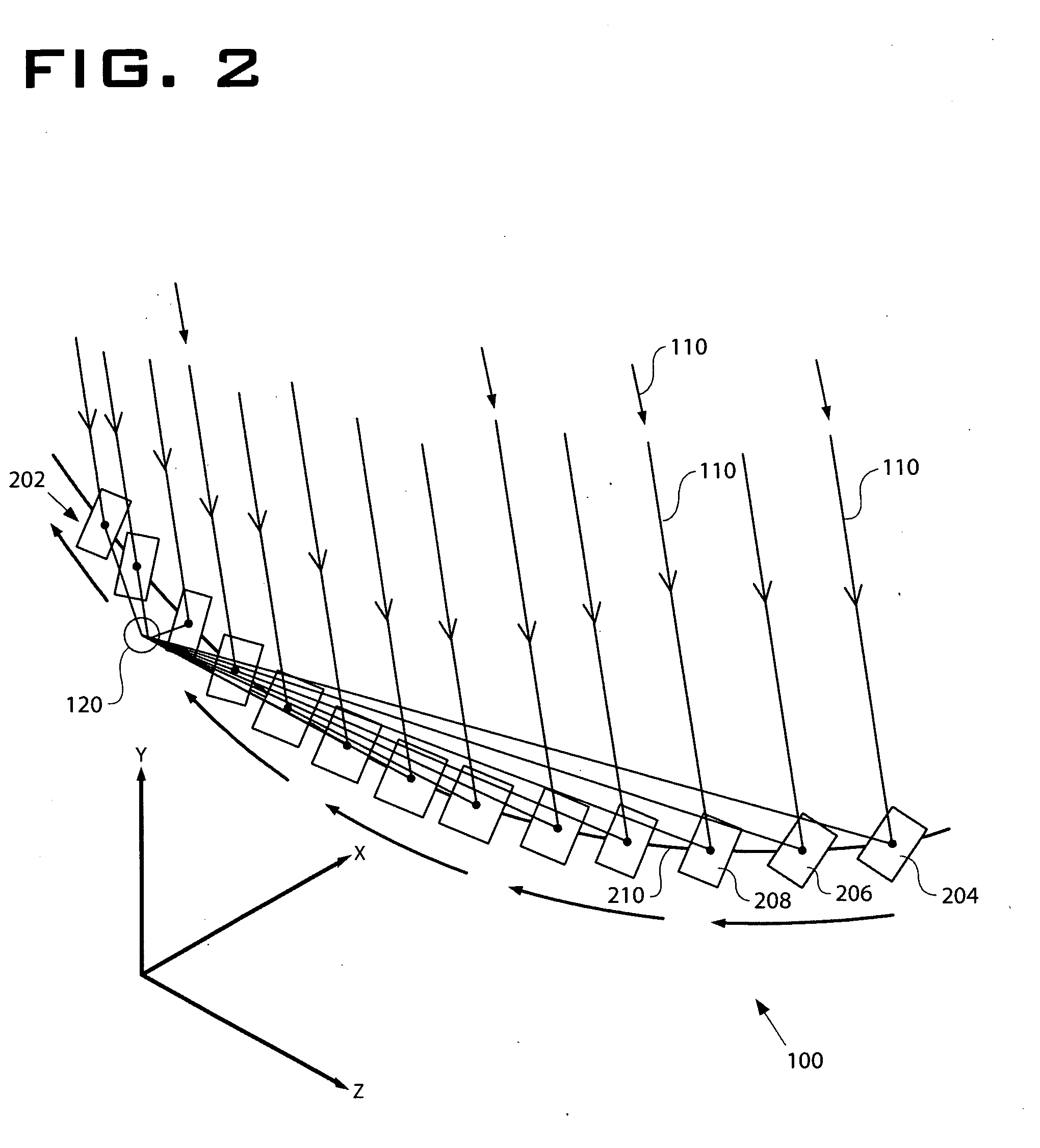
[0043]The solar tracking system 100 provides a system and method for focusing light 110 from a moving light source—such as the Sun—to a stationary focus point using a discrete planar mirror array or mirror family 202 as shown in FIG. 2. In one embodiment, the mirror family 202 and the mirror path reside in a single horizontal plane. A mirror with a given orientation, which includes tilt and rotation, will reflect source light to the focus at one instant in time. If the mirror is left stationary, the reflected beam will fall off the focus or target area or target locati...


PUM


Abstract

A tracking system for reflecting electromagnetic radiation from a source to a target area, having at least one reflecting surface or mirror mounted to a support that fixes the reflecting surface orientation to focus electromagnetic radiation on the target area when the reflecting surface is at a first location at a first predefined time. The system has a path with at least the first location and a second location. The reflecting surface is movable along the path to maintain focus on the target area. The reflecting surface may have an orientation with a fixed declination angle and fixed hour angle. The source may include a moving source such as the Sun.

Description

FIELD OF THE INVENTION[0001]The invention involves focusing electromagnetic radiation from a source to a target.BACKGROUND OF THE INVENTION[0002]When a stationary light source or an electromagnetic radiation source impinges a planar mirror, the reflection of the light source is projected along a line defined by the location of the mirror relative to the light source, and the orientation of the mirror plane relative to the light source. Placing a screen in the path of the reflected light will show an image of the light source on the screen at a specific location relative to the mirror and source locations. Keeping these four attributes constant (source location, mirror location, mirror plane orientation, screen location) will result in the source image on the screen to remain stationary.[0003]If the location of the light source, the location of the planar mirror, the orientation of the mirror plane or the location of the screen is changed, the image of the light source on the screen ...

Claims


Application Information

Patent Timeline
IPC IPC(8): G02B7/198
CPCF24J2/38F24J2/5266F24J2002/1076Y02E10/47F24J2002/5462G02B7/1827G02B7/183F24J2002/385F24S30/20F24S2030/134F24S50/20F24S2023/87F24S2050/25
Inventor GREEN, STEVEN RUSSELL
Owner GREEN STEVEN RUSSELL
Why Eureka
Try Eureka