Full-range-duty pwm signal generation method, apparatus, and system using same

a pwm signal and full-range technology, applied in the direction of electric variable regulation, process and machine control, instruments, etc., can solve the problems of increasing production cost, emi problem, and pwm signal duty cycle v/sub>out, so as to achieve the effect of improving production cost and improving emi problem

Inactive Publication Date: 2010-08-05
GRENERGY OPTO INC
View PDF5 Cites 6 Cited by
  • Summary
  • Abstract
  • Description
  • Claims
  • Application Information

AI Technical Summary

Benefits of technology

[0017]The primary objective of the present invention is to provide a full-range-duty PWM signal generation method for an AC-to-DC power conversion so that when the electronic equipment enters power saving mode, the PWM signal can automatically issue a zero duty cycle without the need of any additional control signal, additional load sensing circuit or any additional switch circuit.
[0018]Another objective of the present invention is to further provide a full-range-duty PWM signal generation apparatus for an AC-to-DC power conversion so that when the electronic equipment enters power saving mode, the full-range-duty PWM signal generation apparatus can automatically produce a PWM signal of zero duty cycle without the need of any additional control signal, additional load sensing circuit or any additional switch circuit.
[0019]Still another objective of the present invention is to further provide a system using a full-range-duty PWM signal generation apparatus for an AC-to-DC power conversion so that when the electronic equipment enters power saving mode, the full-range-duty PWM signal generation apparatus can automatically produce a PWM signal of zero duty cycle without the need of any additional control signal, additional load sensing circuit or any additional switch circuit.
[0023]To make it easier for our examiner to understand the objective of the invention, its structure, innovative features, and performance, we use a preferred embodiment together with the accompanying drawings for the detailed description of the invention.

Problems solved by technology

In addition, since the output error signal has a minimum DC bias, the duty cycle of the PWM signal Vout therefore can never be reduced to zero.
However, there are some drawbacks corresponding to this solution.
First, the additional switch circuit utilizing a relay or a power MOSFET for cutting off the power conduction path will increase production cost.
Second, the additional switch circuit may result in worsen EMI problem.
Third, the additional switch circuit may decrease the conversion efficiency.
Fourth, the additional switch circuit may increase the heat production.
However, there are also some drawbacks corresponding to this solution.
First, the circuit topology will become much more complex due to the extra implementation of load sensing circuit and switch circuit in the AC-to-DC power adapter.
Second, the additional switch circuit may cause the same problems as mentioned in the previous paragraph.

Method used


Image

  • Full-range-duty pwm signal generation method, apparatus, and system using same
  • Full-range-duty pwm signal generation method, apparatus, and system using same
  • Full-range-duty pwm signal generation method, apparatus, and system using same

Examples


Embodiment Construction

[0029]The present invention will be described in more detail hereinafter with reference to the accompanying drawings that show the preferred embodiment of the invention.

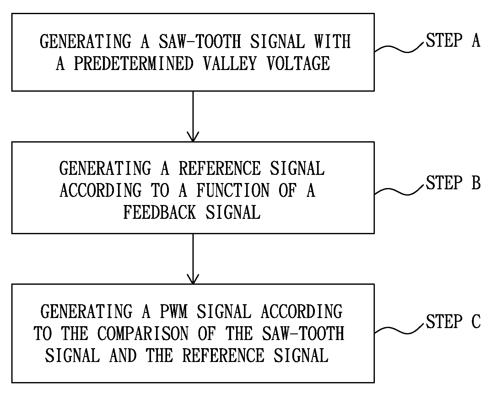
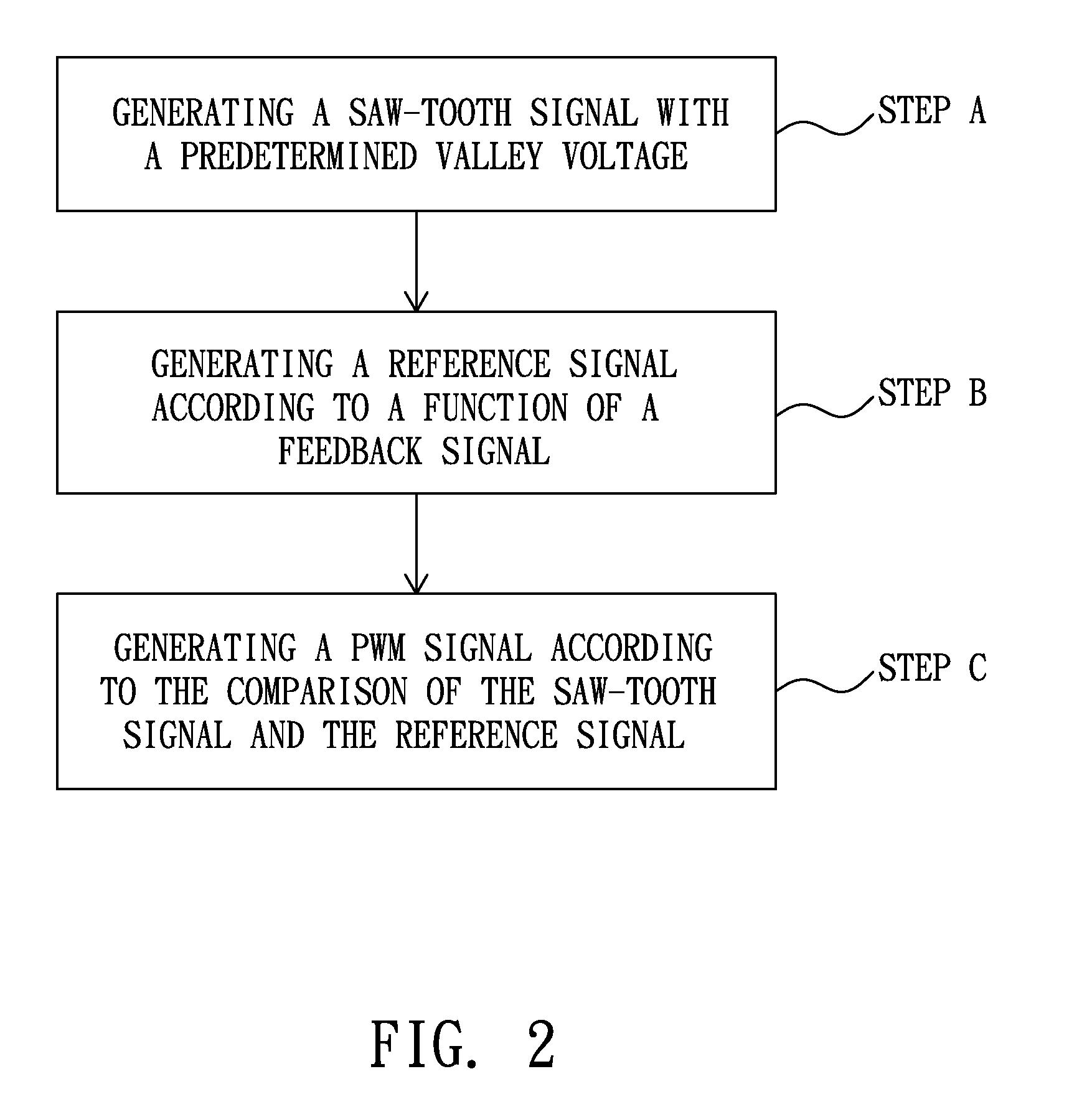
[0030]Please refer to FIG. 2, which shows the flow chart of a full-range-duty PWM signal generation method for an AC-to-DC power conversion according to a preferred embodiment of the present invention. As shown in FIG. 2, the full-range-duty PWM signal generation method includes the steps of: generating a saw-tooth signal with a predetermined valley voltage (step A); generating a reference signal according to at least one of a current feedback signal and a voltage feedback signal (step B); and generating a PWM signal according to the comparison of the saw-tooth signal and the reference signal (step C).

[0031]In step A, the saw-tooth signal is generated across a capacitor by connecting the capacitor with an adaptive current source and a switching pull-low circuit.

[0032]The adaptive current source is generated according...


PUM


Abstract

The present invention discloses a full-range-duty PWM signal generation method for an AC-to-DC power conversion, comprising the steps of: generating a saw-tooth signal with a predetermined valley voltage; generating a reference signal according to at least one of a current feedback signal and a voltage feedback signal; and generating a PWM signal according to voltage comparison of the saw-tooth signal and the reference signal. Furthermore, the present invention also provides a full-range-duty PWM signal generation apparatus for an AC-to-DC power conversion, and a system using the full-range-duty PWM signal generation apparatus.

Description

BACKGROUND OF THE INVENTION[0001]1. Field of the Invention[0002]The present invention relates to AC-to-DC power conversion, and more particularly to AC-to-DC power conversion with power saving mode.[0003]2. Description of the Related Art[0004]In supplying the power for electronic equipments, such as desk-top computers or notebook computers, the AC-to-DC power adapter is widely adopted. Due to the green-mode requirement or power saving demand that has become a trend, the AC-to-DC power adapter should possess power-down function when the electronic equipment enters a power saving mode.[0005]FIG. 1 shows the architecture of a typical AC-to-DC power adapter. As shown in FIG. 1, the architecture realizing a fly-back type AC-to-DC power converter, at least includes: a PWM controller 100, an input rectifier and filter 101, a main transformer 102, an output rectifier and filter 103, a feedback network 104, and an NMOS transistor 105.[0006]In the architecture, the PWM controller 100 is used ...

Claims


Application Information

Patent Timeline
Patent Type & Authority Applications(United States)
IPC IPC(8): H02M3/315
CPCH02M3/33507Y02B70/16H02M2001/0032H02M1/0032Y02B70/10
Inventor LIN, KO-MING
Owner GRENERGY OPTO INC
Why Eureka
Try Eureka