Optical storage medium comprising tracks with positive and negative marks, and stampers and production methods for manufacturing of the optical storage medium

a technology of optical storage medium and positive and negative marks, which is applied in the field of optical storage medium, can solve the problems of reducing the effective size of the light spot used for reading or writing to the optical storage medium, and not allowing to reduce the track pitch, so as to achieve the effect of reducing the effective period of the track pitch, and reducing the track pitch between two neighboring tracks

Inactive Publication Date: 2010-08-05
THOMSON LICENSING SA
View PDF14 Cites 0 Cited by
  • Summary
  • Abstract
  • Description
  • Claims
  • Application Information

AI Technical Summary

Benefits of technology

[0010]A positive mark corresponds for example with a bump and a negative mark with a pit. The mark structure between neighboring tracks is hence alternating, and the effective period of the track pitch is therefore doubled. When using an optical pick-up for reading of the data, the pick-up can focus either on tracks having positive marks, or on tracks having negative marks. The track pitch of the optical storage medium can be reduced therefore by about a factor of two for a respective pick-up, without changing the design of the pick-up. When using a Blu-Ray type pick-up, the track pitch between two neighboring tracks can be reduced therefore below its optical resolution limit of 280 nm, for example to a value within a range of 150-250 nm.

Problems solved by technology

This is possible by using a so-called Super-RENS structure or layer, which is placed above the data layer of the optical storage medium, and which significantly reduces the effective size of a light spot used for reading from or writing to the optical storage medium.
The super RENS effect allows to increase the resolution of the optical pickup for reading of the marks on an optical disc in track direction, but does not allow to reduce the track pitch.

Method used


Image

  • Optical storage medium comprising tracks with positive and negative marks, and stampers and production methods for manufacturing of the optical storage medium
  • Optical storage medium comprising tracks with positive and negative marks, and stampers and production methods for manufacturing of the optical storage medium
  • Optical storage medium comprising tracks with positive and negative marks, and stampers and production methods for manufacturing of the optical storage medium

Examples


Embodiment Construction

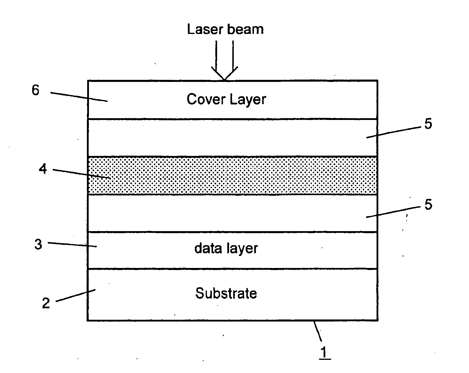
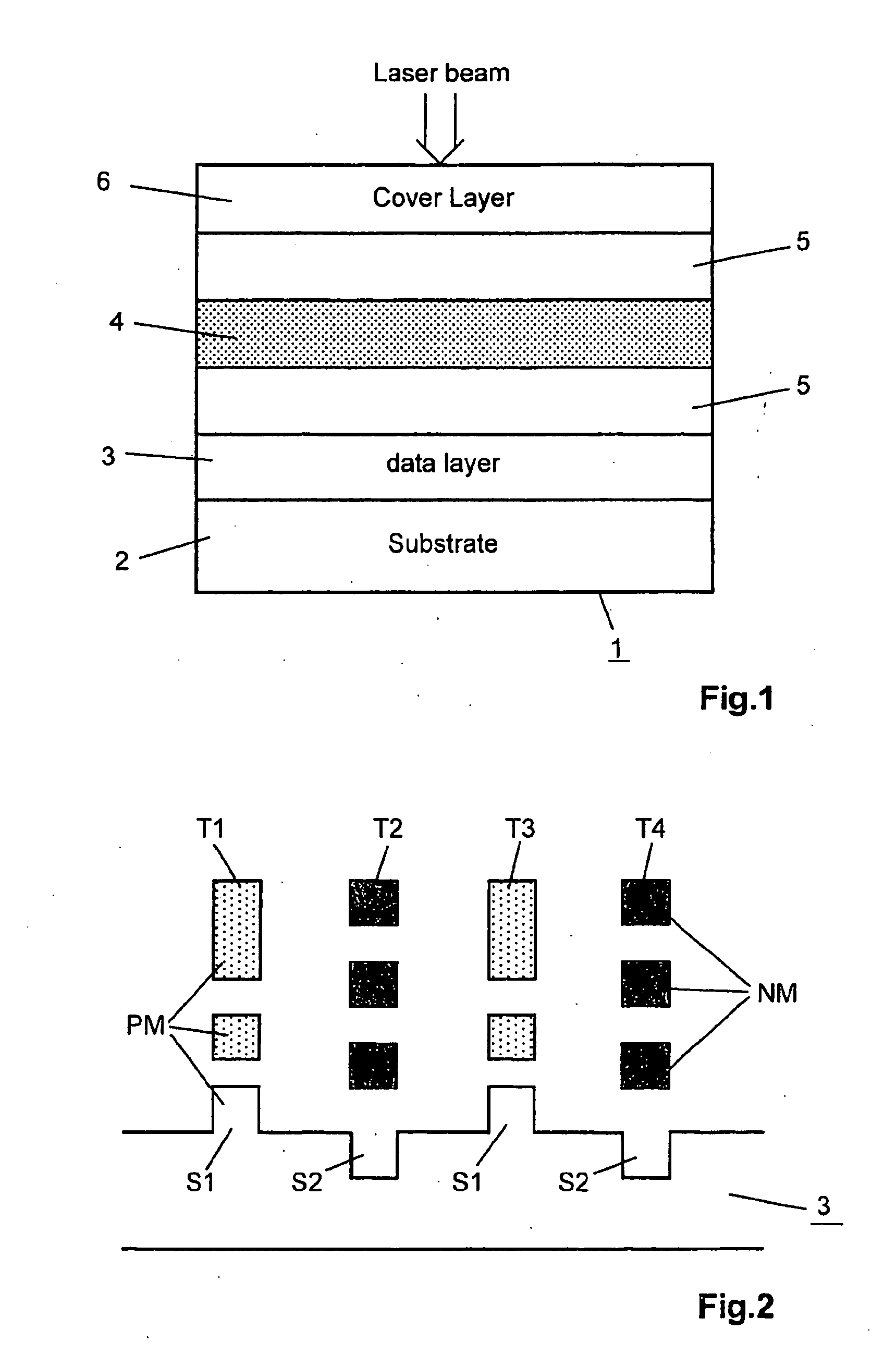
[0020]In FIG. 1 a read-only optical storage medium 1 is shown in a cross section in a simplified manner. On a substrate 2 a read-only data layer 3 is arranged comprising a reflective metallic layer, for example an aluminum layer, data layer 3 having a data structure consisting of marks and spaces arranged on essentially parallel tracks. On the data layer 3 a first dielectric layer 5 is arranged and on the dielectric layer 5 a mask layer 4 is arranged for providing a super-resolution near-field effect (Super-RENS). The optical storage medium 1 is in particular an optical disc having a size similar to DVDs and CDs for example.

[0021]Above the mask layer 4 a second dielectric layer 5 is arranged. As a further layer, a cover layer 6 is arranged on the second dielectric layer 5 as a protective layer. For reading the data of the data layer, 3, a laser beam is applied from the top of the storage medium 1, penetrating first the cover layer 6. The first and second dielectric layers 5 comprise...


PUM

PropertyMeasurementUnit
laser wavelengthaaaaaaaaaa
lengthaaaaaaaaaa
lengthaaaaaaaaaa

Abstract

The optical storage medium comprises a substrate layer, a data layer with a mark/space structure arranged in tracks on the substrate layer, and a cover layer. One track comprises positive marks and a neighboring track comprises negative marks. The tracks are arranged in particular as spirals wherein one spiral contains a track with only positive marks and a neighboring spiral contains a track with only negative marks. The positive marks of a track and correspondingly the negative marks of a track are separated each by spaces. The optical storage medium is particularly a read-only optical disc and comprises a mask layer with a super resolution near field structure, wherein the tracks of the data layer are arranged as two spirals, one spiral consisting of positive marks only and the other spiral consisting of negative marks only. For the production of the optical storage medium, a stamper and production methods for a master for a stamper production are provided, comprising a surface with positive and negative marks, which correspond to the respective positive and negative marks of the data layer of the optical storage medium.

Description

TECHNICAL FIELD OF THE INVENTION[0001]The present invention relates to an optical storage medium, which comprises a substrate layer, a read-only data layer with a mark / space structure arranged in tracks on the substrate layer and a cover layer, and to a respective production of the optical storage medium. The optical storage medium comprises in particular also a mask layer with a super resolution near field structure for storing of data with a high data density.BACKGROUND OF THE INVENTION[0002]Optical storage media are media in which data are stored in an optically readable manner, for example by means of a pickup comprising a laser for illuminating the optical storage medium and a photo-detector for detecting the reflected light of the laser beam when reading the data. In the meanwhile a large variety of optical storage media are available, which are operated with different laser wavelength, and which have different sizes for providing storage capacities from below one Gigabyte up ...

Claims


Application Information

Patent Timeline
Patent Type & Authority Applications(United States)
IPC IPC(8): G11B7/24G11B7/24059G11B7/24065G11B7/24079G11B7/24085G11B7/24091
CPCG11B7/24G11B7/24079G11B7/263G11B7/261G11B7/24085G11B7/24073G11B7/26G11B7/013B29D17/00
Inventor KNITTEL, JOACHIMSTEPHAN, KNAPPMANN
Owner THOMSON LICENSING SA
Why Eureka
Try Eureka