Systems and methods for characterizing transmission lines using broadband signals in a multi-carrier DSL environment

a technology of broadband signal and transmission line, applied in the field of transmission line characteristics determination, can solve the problems of degrading the performance of dsl service, high data transmission rate, rapid and widespread deployment, etc., and achieves the effect of reducing the cost associated, high data rate, and completing the necessary processing and manipulation of digital data quickly and efficiently

Inactive Publication Date: 2010-08-05
AVAGO TECH INT SALES PTE LTD
View PDF21 Cites 9 Cited by
  • Summary
  • Abstract
  • Description
  • Claims
  • Application Information

AI Technical Summary

Benefits of technology

[0009]There may be other sources of noise in a telephone line which are caused by the reception of electromagnetic (EM) waves transmitted by various sources such as AM radio stations, electrical devices such as hair dryers, dimmer switches, alarm systems, or the like. The most detrimental of these electromagnetic sources are generally the AM radio stations. Since no two telephone lines are the same, and the availability and the quality of a DSL link is directly proportional to the conditions of the line as described above, it is important to be able to qualify telephone lines for DSL service and maintain the communications link once the service is established. To decrease the costs associated with service qualification and maintenance, it may be desirable to qualify and maintain telephone lines remotely, without having to send a technician to the customer premises.
[0010]Establishing a communications link between a user and one or more servers connected to the backbone of the central office requires a DSL transceiver to handle the data transmission in accordance with the basic principles outlined above. Each of the transceivers at either side of the link, i.e., the CO and the CPE, are called modems. The CO and the CPE modems comprise some analog hardware to perform analog signal transmission and reception, and a digital section which comprise a digital signal processing (DSP) chip and, for example, an Applications Specific Integrated Circuit (ASIC) that handles signal processing operations. Because of the high data rate associated with DSL service, the DSP chip should be able to complete the necessary processing and manipulation of digital data quickly and efficiently. An exemplary embodiment of the present invention takes advantage of the vast computational capacity of DSL modems and the presence of the DSP chips at the two sides of the transmission line to characterize the transmission line. While the DSL modems can operate as a modem in their usual state, they are also capable of operating in a separate mode where they can be used as test and measurement devices.

Problems solved by technology

Although the multi-carrier DSL systems are promising because they offer a cost-effective way of opening current telephone lines to high-speed data transmission traffic, there are important problems in the installation and maintenance phases of DSL deployment that prevent rapid and widespread deployment.
At high frequencies, line conditions that do not affect the voice transmission become important factors limiting the digital data transmission rate.
Additionally, small, open-circuited, twisted pairs, called bridged taps, connected in shunt with working twisted pairs, while not affecting voice transmission, cause periodic dips in the attenuation function of the line at certain sub-bands and hence degrade the performance of the DSL service.
These signals are perceived as additive noise components because they are unpredictable and meaningless for all but one of the telephone line carrying the actual service.
There may be other sources of noise in a telephone line which are caused by the reception of electromagnetic (EM) waves transmitted by various sources such as AM radio stations, electrical devices such as hair dryers, dimmer switches, alarm systems, or the like.
The most detrimental of these electromagnetic sources are generally the AM radio stations.

Method used


Image

  • Systems and methods for characterizing transmission lines using broadband signals in a multi-carrier DSL environment
  • Systems and methods for characterizing transmission lines using broadband signals in a multi-carrier DSL environment
  • Systems and methods for characterizing transmission lines using broadband signals in a multi-carrier DSL environment

Examples


Embodiment Construction

[0041]The exemplary embodiments of this invention will be described in relation to the application of the invention to an ADSL transceiver environment. However, it should be appreciated that in general the systems and methods of this invention will work equally well for any multicarrier communication system including, but not limited to DSL, VDSL, SDSL, HDSL, HDSL2, or any other discrete multi-tone or discrete wavelet multi-tone DSL system.

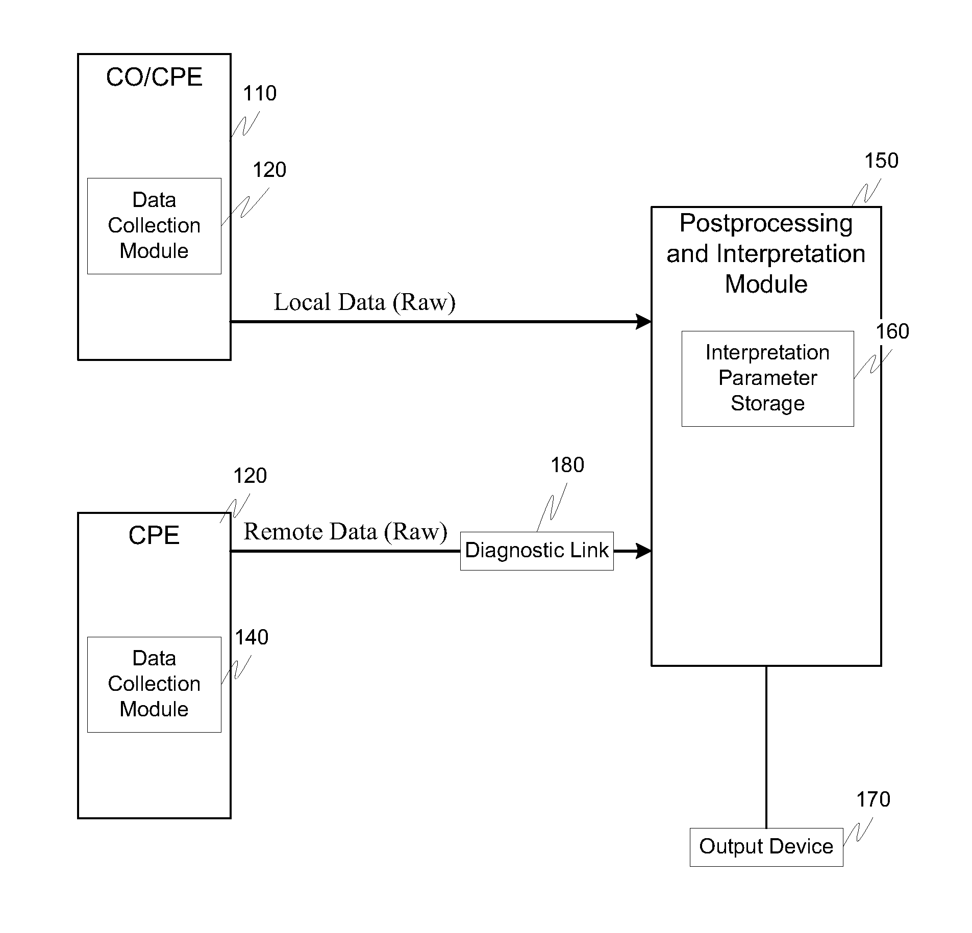
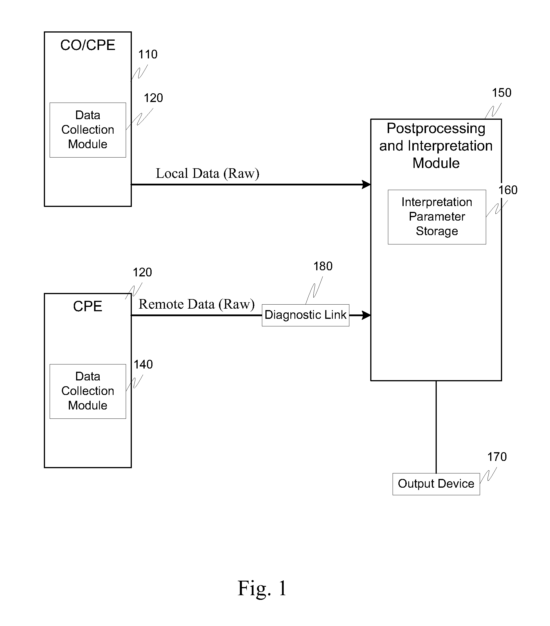
[0042]FIG. 1 illustrates an exemplary line characterization system 100. The line characterization system 100 comprises one or more CO modems 110, one or more CPE modems 130 and a postprocessing and interpretation module 150. Additionally, the CO modem 110 comprises a data collection module 120. Likewise, the CPE modem 130 comprises a data collection module 140. The processing and interpretation module 150 comprises an interpretation parameter storage 160 and is connected to one or more output devices 170.

[0043]For ease of illustration, the standar...


PUM


Abstract

Using DSL modems as data collectors, the modems processes the data to, for example, allow easier interpretation of the line characteristics. In particular, the modems postprocess the data including calibration, filter compensation, determination of the SNR medley from the bits and gains tables and rate conversion. The interpretation process uses the postprocessed data and determines loop characterization, interferer detection, a data reduction estimation and a data rate estimation. The outputs of these determinations least allow for the characterization of the line conditions between the two modems.

Description

RELATED APPLICATION DATA[0001]This application claims the benefit of and priority to U.S. Provisional Application Ser. No. 60 / 224,308 filed Aug. 10, 2000 entitled “Characterization of Transmission Lines Using Broadband Signals in a Multi-Carrier DSL System” and is related to U.S. patent application Ser. No. 09 / 755,172, filed Jan. 8, 2001 entitled “Systems and Methods for Loop Length and Bridged Tap Length Determination of a Transmission Line” and U.S. patent application Ser. No. 09 / 755,173, filed Jan. 8, 2001, entitled “Systems and Methods for Establishing a Diagnostic Transmission Mode and Communicating over the Same,” all of which are incorporated herein by reference in their entirety.BACKGROUND OF THE INVENTION[0002]1. Field of the Invention[0003]In general, the systems and methods of this invention relate to the determination of transmission line characteristics. In particular, this invention relates to systems and methods for determining the characteristics of a transmission li...

Claims


Application Information

Patent Timeline
Patent Type & Authority Applications(United States)
IPC IPC(8): H04B17/00H04B3/06H04L1/00H04L1/18H04L1/24H04L5/14H04L29/10H04M3/22H04M3/30
CPCH04B3/46H04L1/0002H04L1/18H04L1/24H04L1/245H04L5/0046H04B3/487H04L25/0202H04M3/2209H04M3/2227Y02B60/31H04M3/306H04L5/1438Y02D30/50H04L12/16
Inventor BELGE, MURATTZANNES, MICHAEL A.PADIR, HALIL
Owner AVAGO TECH INT SALES PTE LTD
Why Eureka
Try Eureka