Grinding device using ultrasonic vibration

Inactive Publication Date: 2010-08-05
OHNISHI KAZUMASA
View PDF6 Cites 10 Cited by
  • Summary
  • Abstract
  • Description
  • Claims
  • Application Information

AI Technical Summary

Benefits of technology

[0008]It is an object of the present invention to provide a grinding machine utilizing ultrasonic vibration, which can grind an object with high accuracy.
[0009]As a result of studies by the inventor, it has been discovered that when the annular elastic body having a grind stone on the bottom surface is connected to a base portion of the rotating shaft for rotating the grind stone with a connection plate having a connection means comprising alternately formed connection sections and space sections on a bottom surface thereof, portions of the elastic body between the adjoining connection sections show larger ultrasonic vibration than portions in the vicinity of the connection sections. It has been further discovered that if a ultrasonic vibrator is placed on the former portions to generate ultrasonic vibration, the ultrasonic vibration hardly escapes to the rotating shaft and hence most of the ultrasonic vibration are transmitted to the grind stone through the annular elastic body to increase grind accuracy.
[0021]The grinding machine of the invention has a connection plate between an annular elastic body having a grind stone on its bottom surface and a base portion of a rotating shaft for rotating the grind stone, under such condition that the annular elastic body is connected to the connection plate through connection means comprising alternately formed connection sections and space sections. Ultrasonic vibrations generated by a plurality of ultrasonic vibrators placed on the annular elastic body at the predetermined positions hardly escape into the rotating shaft through the connection sections (and connection plate) and a most portion of the ultrasonic vibrations are transmitted to the grind stone through the annular elastic body because the elastic body vibrates with a larger amplitude in areas facing the space sections than in areas connected to the connection sections. Therefore, the grinding machine of the invention can grind an object with high accuracy.

Problems solved by technology

It has been found by the present inventor, however, that a portion of ultrasonic vibration generated by the laminated piezoelectric actuator of the above-mentioned grinding machine is apt to escape into the grinding shaft through the elastic body and hence that a sufficiently large ultrasonic vibration cannot be transmitted to the grind stone.
If the ultrasonic vibration transmitted to the grind stone is not sufficiently large, frictional resistance between the grind stone and the object to be ground increases and hence inappropriate mechanical vibration is generated when these are brought into rubbing contact, to decrease the grind accuracy (i.e., the object having been ground has a rough surface).

Method used


Image

  • Grinding device using ultrasonic vibration
  • Grinding device using ultrasonic vibration
  • Grinding device using ultrasonic vibration

Examples


Embodiment Construction

[0049]The grinding machine of the invention is described below, referring to the attached drawings.

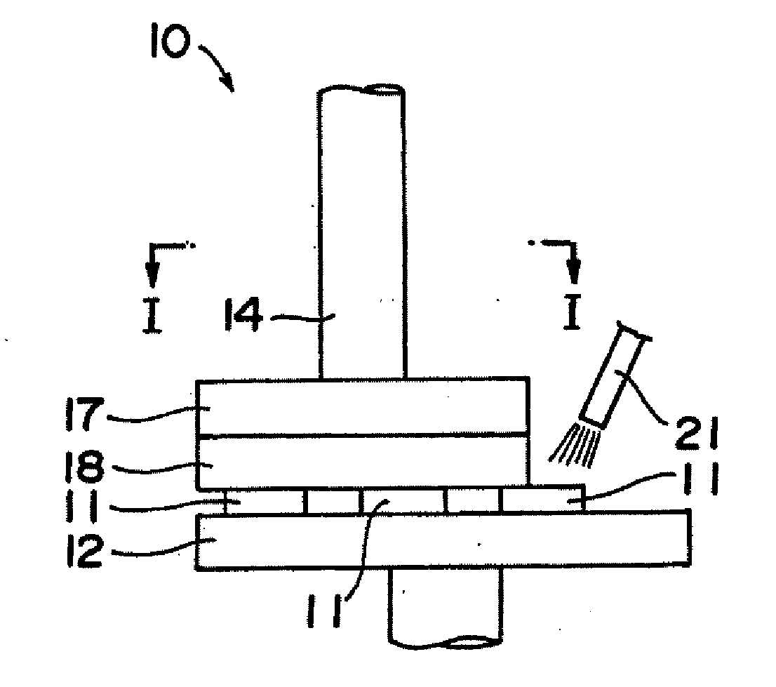
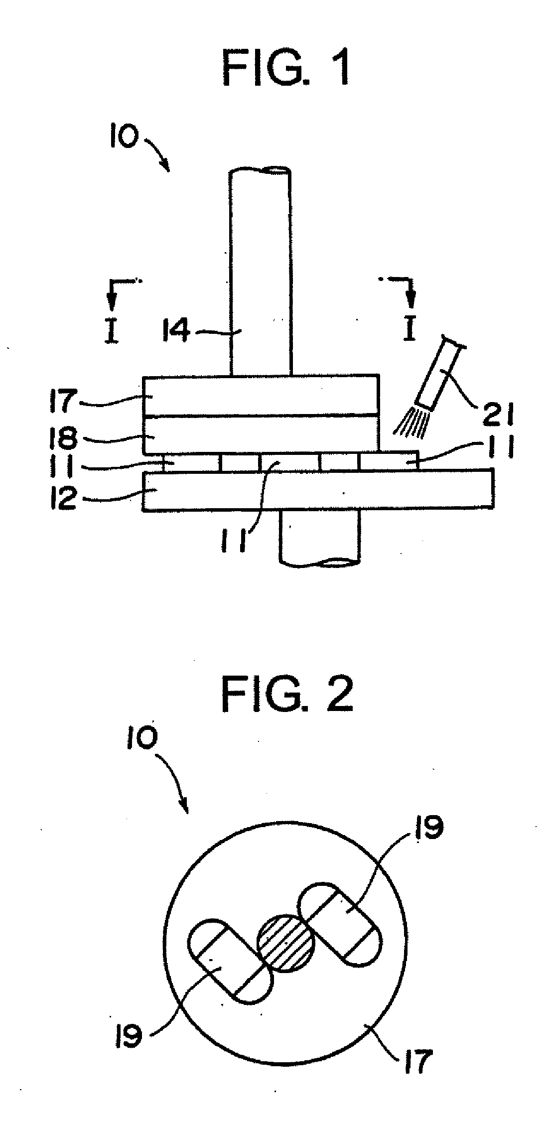
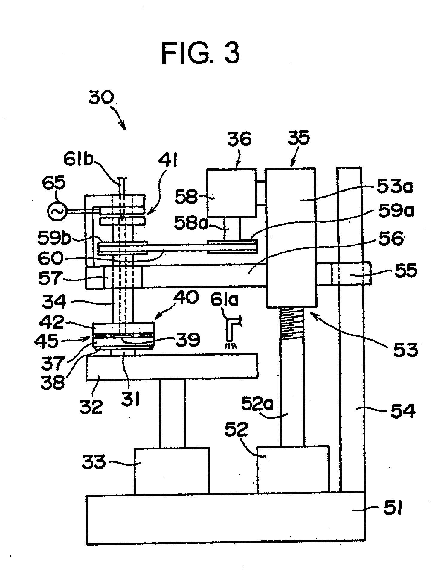
[0050]FIG. 3 is a front view of a grinding machine according to the invention. FIG. 4 is an enlarged view illustrating the grinding tool 40 of the grinding machine 30 of FIG. 3 which comprises a connection plate 42, connection means 45, annular elastic body 37, ultrasonic vibrators 39 and grind stone 38. FIG. 5 is a perspective exploded view of the grinding tool 40 of FIG. 4. FIG. 6 is a top view illustrating the annular elastic body 37, ultrasonic vibrators 39 and grind stone 38 which constitute the grinding tool 40 of FIG. 4. FIG. 7 is a sectional view illustrating the annular elastic body 37, ultrasonic vibrators 39 and grind stone 38 taken along the line II-II shown in FIG. 6.

[0051]As is illustrated in FIGS. 3 to 7, the grinding machine 30 comprises a support table 32 on which an object 31 to be ground is supported and fixed, a vertically movable rotating shaft 34 arranged above th...


PUM

PropertyMeasurementUnit
Electric energyaaaaaaaaaa
Lengthaaaaaaaaaa
Areaaaaaaaaaaa

Abstract

A grinding device (30) for grinding an object (31) at high accuracy has a support table (32) on which the object (31) is supported and fixed, a vertically movable rotating shaft (34) arranged above the support table, a drive device (35) for vertically moving the rotating shaft, a drive device (36) for rotating the rotating shaft, an elastic body (37) fixed to a base section of the rotating shaft, an annular grind stone (38) provided to a bottom of the elastic body, ultrasonic vibrators (39) arranged on the elastic body, and a transmission unit (41) for transmitting electric energy to the ultrasonic vibrators, in which the elastic body is an annular elastic body and a connection plate (42) is provided between the annular elastic body and the base section of the rotating shaft under such condition that the connection plate and the annular elastic body are connected by connection means (45) having alternately arranged connection sections and space sections and each ultrasonic vibrator is arranged at a predetermined position of the elastic body.

Description

FIELD OF THE INVENTION[0001]This invention relates to a grinding machine utilizing ultrasonic vibration which is employable for grinding a surface of an object such as glass body or silicon body to give a smoothened surface.BACKGROUND OF THE INVENTION[0002]Heretofore, various substrates such as a glass substrate, a silicon substrate and a silicon nitride substrate are employed for manufacturing thin film electronic devices. These substrates are ground on their surfaces using a grinding machine to give smoothened surfaces. In addition, optical devices such as a lens and a prism can be ground to give smoothened surfaces. It is known that a grinding machine utilizing ultrasonic vibration is employable for grinding these objects on their surface to give smoothened surface or to adjust the thickness of the object by repeated grinding procedures.[0003]FIG. 1 is a front view of a conventional grinding machine illustrated in Japanese Patent Provisional Publication 5-200,659. FIG. 2 is a sec...

Claims


Application Information

Patent Timeline
IPC IPC(8): B24B7/07
CPCB24B41/0475B24B1/04
Inventor OHNISHI, KAZUMASA
Owner OHNISHI KAZUMASA
Why Eureka
Try Eureka