Dehumidifying apparatus for dryer
- Summary
- Abstract
- Description
- Claims
- Application Information
AI Technical Summary
Benefits of technology
Problems solved by technology
Method used
Image

Examples
first embodiment
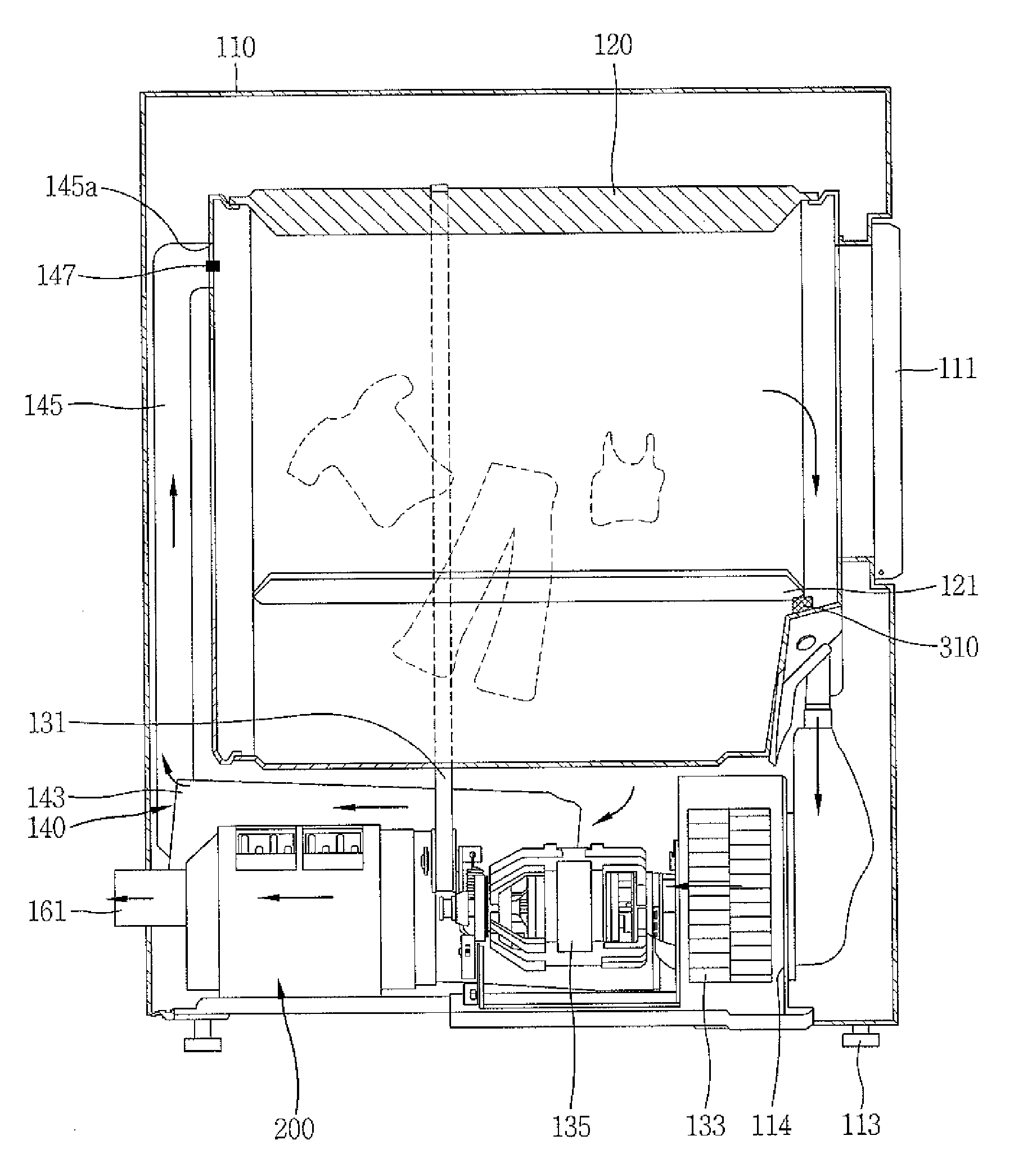
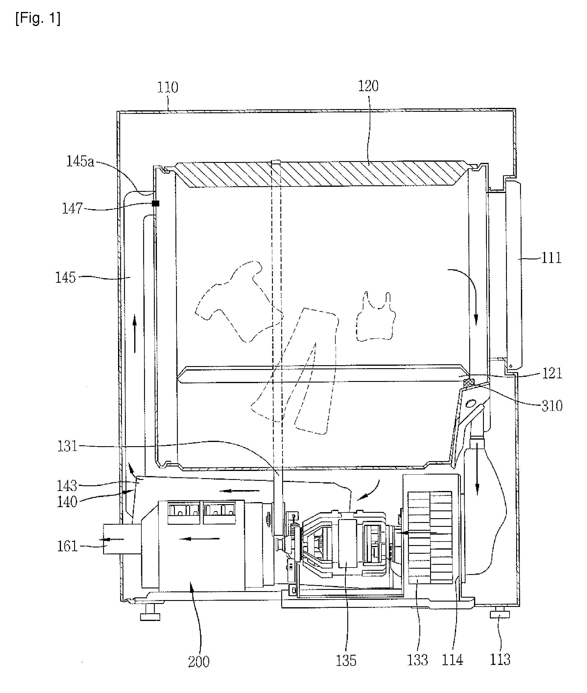
[0024]Referring to FIGS. 1 and 2, the ductless dryer according to the present invention may include a main body 110; a drum 120 rotatably mounted at the main body 110; a hot air supplying unit 140 supplying hot air into the drum 120; a heat exchanger 150 removing moisture contained in the air exhausted from the drum 120; a circulation duct 180 conducting the air exhausted from the drum 120 to the heat exchanger 150; a filter 200 installed in the circulation duct 180 and filtering lint contained in the air coming out of the drum 120; and a sealing unit S preventing the leakage of lint through a gap of an installation portion where the filter 200 is installed.
[0025]A door 111 is mounted on a front surface of the main body 110 to enable loading of clothes into the drum 120. A foot 113 is disposed at a lower portion of the main body 110 to support the main body 110. A belt 131 for rotating the drum 120 and a motor 135 for supplying a driving force to the belt 131 are mounted inside the ...
second embodiment
[0054]FIG. 6 is a schematic cross-sectional view of a dehumidifying apparatus for a dryer according to the present invention.
[0055]Referring to FIG. 6, a water-cooled heat exchange module 410 as a second dehumidifying unit is installed at a rear side of the heat exchanger 150.
[0056]The water-cooled heat exchange module 410 may include a water supply pipe 411, a heat exchange pipe 412, a water drain pipe 413, a heat radiation fin 415, a heat exchange plate 416 and a heat absorption plate 417. That is, the fan and the heat radiation fin in FIG. 5 are replaced with a water-cooled water jacket in the embodiment shown in FIG. 6.
[0057]Cool water introduced into the water supply pipe 411 is configured to cool the heat radiation fin 415 while flowing through the heat exchange pipe 412, and after the heat exchange, to be discharged to the outside through the water drain pipe 413.
[0058]The water supply pipe 411 for supplying water may be separately formed from the refrigerant inlet pipe 251, ...
third embodiment
[0059]FIG. 7 is a schematic cross-sectional view of a dehumidifying apparatus for a dryer according to the present invention.
[0060]Referring to FIG. 7, a thermoelectric module 420 as a second dehumidifying unit is installed at a rear side of the heat exchanger 150. The thermoelectric module 420 may include a thermoelectric element 422 and a fan 421. A heat absorption side of the thermoelectric element is disposed inside the exhaust duct 161, and a heat radiation side thereof is disposed outside the exhaust duct 161.
[0061]If gas flowing through the exhaust duct 161 is cooled by contacting the heat absorption side of the thermoelectric element 422, moisture remaining in the gas is saturated, thereby being condensate water. An outer plate 423 of the thermoelectric element 422 which radiates by the heat exchange is cooled by the fan 421.
PUM
 Abstract
Description
Claims
Application Information
 - R&D Engineer
- R&D Manager
- IP Professional
- Industry Leading Data Capabilities
- Powerful AI technology
- Patent DNA Extraction
Browse by: Latest US Patents, China's latest patents, Technical Efficacy Thesaurus, Application Domain, Technology Topic.
© 2024 PatSnap. All rights reserved.Legal|Privacy policy|Modern Slavery Act Transparency Statement|Sitemap