Device and method for cleaning the core engine of a jet engine

a technology for jet power plants and core engines, which is applied in the direction of cleaning using liquids, cleaning processes and equipment, etc., can solve the problems of contaminated jet power plants, impairing surface quality, and affecting the operation of jet power plants, so as to achieve effective cleaning

Active Publication Date: 2010-08-12
LUFTHANSA TECH AG
View PDF37 Cites 23 Cited by
  • Summary
  • Abstract
  • Description
  • Claims
  • Application Information

AI Technical Summary

Benefits of technology

[0017]The nozzles are preferably flat jet nozzles, but other shapes such as round jet nozzles or a combination of different nozzles can be also be used. The jet plane is preferably oriented in the radial direction, i.e. it is spanned by two axes, of which one points in the radial direction. In this way, the rotating flat jet can sweep over essentially the entire area of the intake of the core engine in an especially effective manner.
[0018]It is additionally preferred that the jet plane with the rotational axis includes an incident angle. This me

Problems solved by technology

Jet power plants, during operation, are contaminated as a result of combustion residues of the core engine, and also as a result of air contaminants which are drawn in with the combustion or bypass air, such as dust, insects, saline fog, or other environmen

Method used


Image

  • Device and method for cleaning the core engine of a jet engine
  • Device and method for cleaning the core engine of a jet engine
  • Device and method for cleaning the core engine of a jet engine

Examples


Embodiment Construction

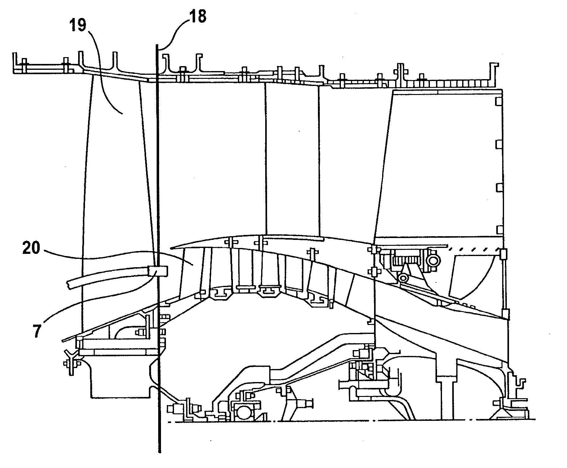
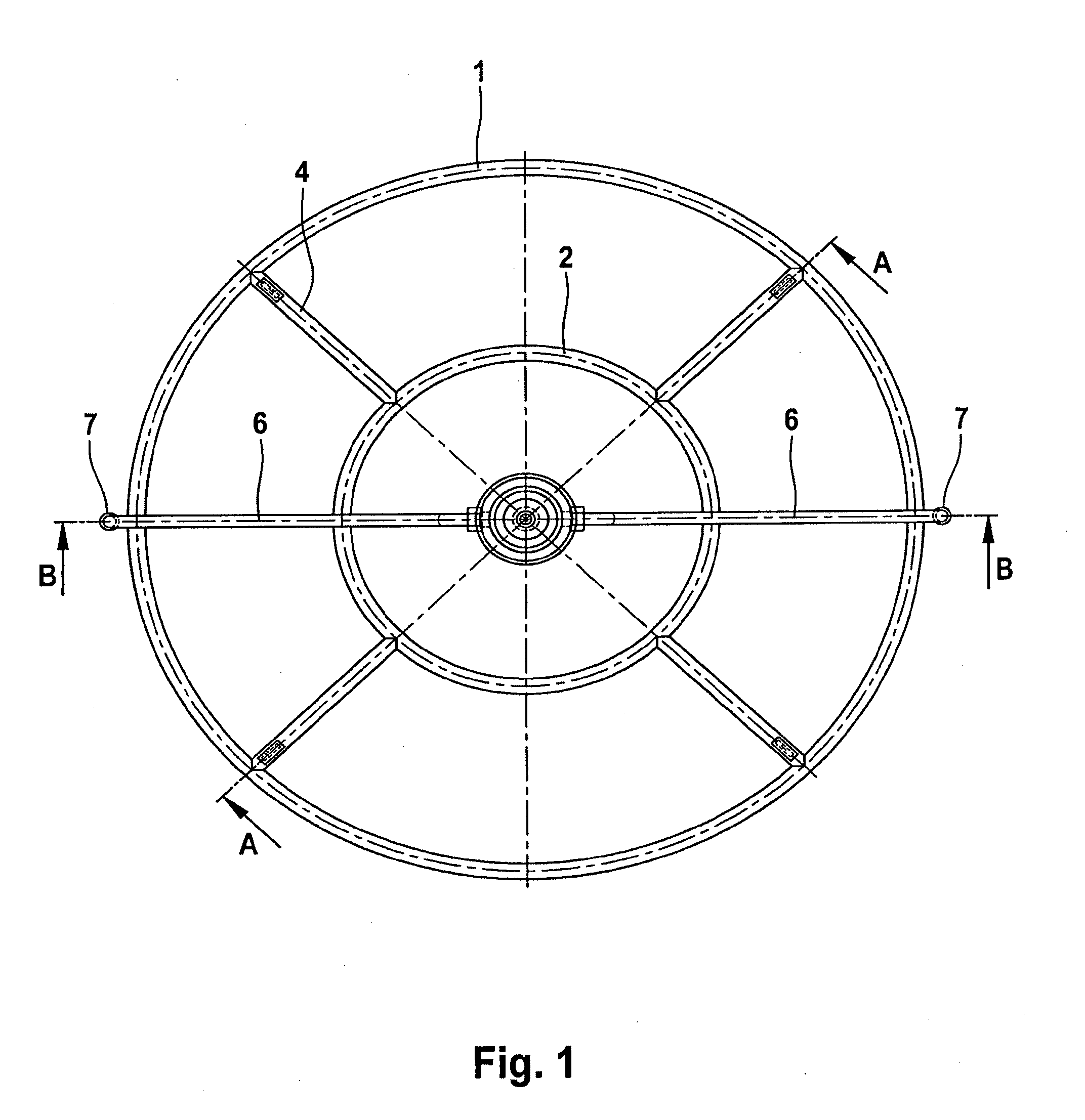
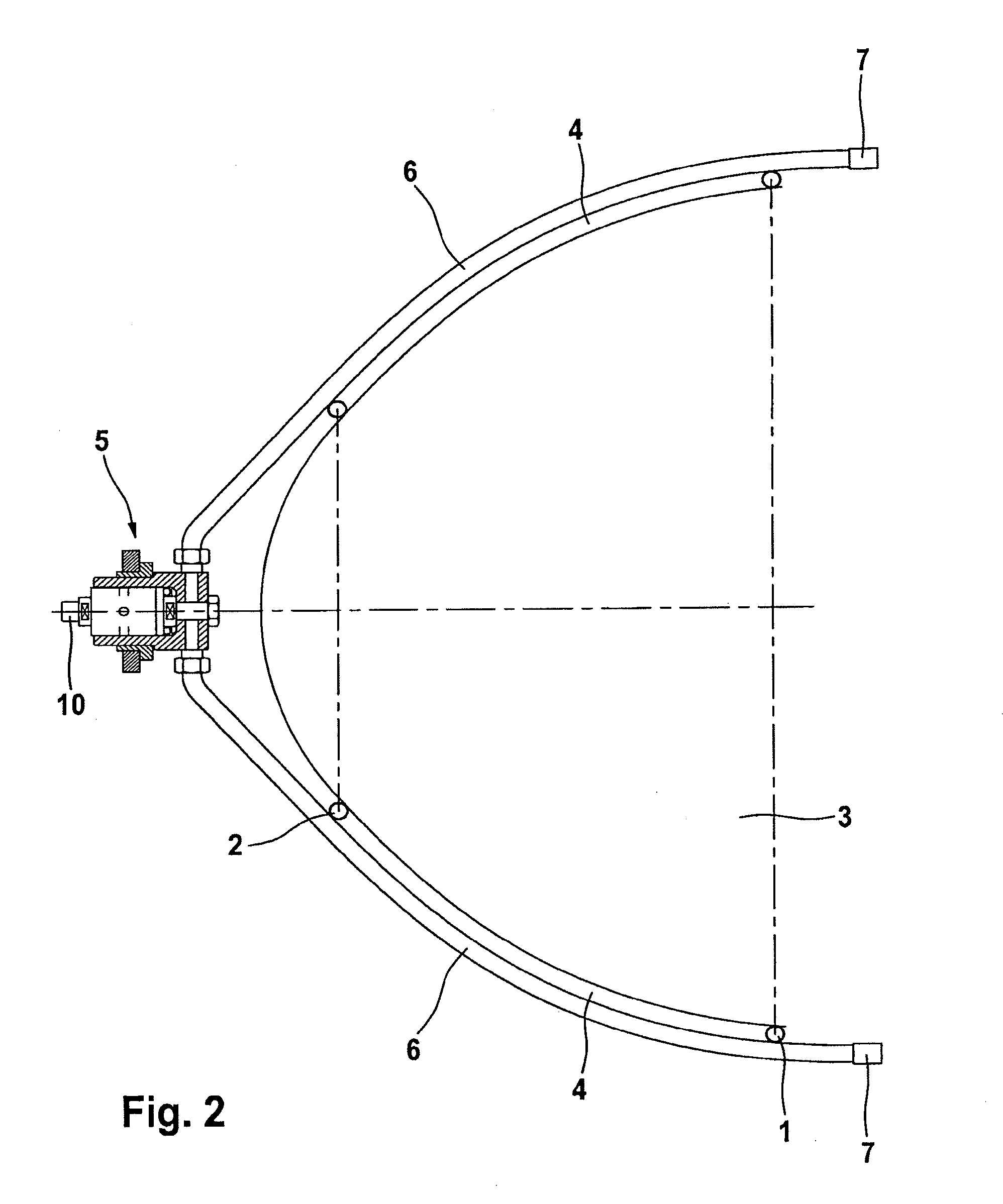
[0050]The nozzle unit has two ring elements 1, 2 by means of which the nozzle unit is seated on a shaft hub 3 of the fan of a jet power plant (see FIGS. 2 and 3). In the seated state, the ring elements 1, 2 encompass the shaft hub 3 in an essentially form-fitting manner. The two ring elements 1, 2 are interconnected by means of radial struts 4. A rotary joint, which as a whole is designated 5, is arranged on the point of the nozzle unit which points upstream (with regard to the flow direction of the power plant). From this rotary joint extend two radially outwardly leading pressure lines 6 which supply two flat jet nozzles 7 with cleaning medium. In the detailed view of FIG. 4 it is to be seen that the two pressure lines 6, via radial passages 8 and an axial passage 9 of the rotary joint 5, are in fluid communication with a feed line 10 which connects the rotary joint to the supply unit, which is not shown in the drawing.

[0051]The pressure lines 6 are fixed at the crossover points w...


PUM


Abstract

The object of the invention is a device for cleaning the core engine of a jet engine, having a supply unit, which provides the cleaning medium, a nozzle unit, which is configured for feeding the cleaning medium into the core engine, and a line connection between the supply unit and the nozzle unit. The invention provides that the nozzle unit has a means for the rotationally fixed connection to the fan shaft of the jet engine, and that a rotary coupling is provided between the nozzle unit and the line connection. The object of the invention is further an arrangement of such a device and a turbo fan jet engine, and a method for cleaning the core engine of a jet engine using the device.

Description

REFERENCE TO RELATED APPLICATIONS[0001]This application is a continuation of U.S. Ser. No. 12 / 302,682, filed Nov. 26, 2008, which is the national stage under 35 USC 371 of International Application No. PCT / EP2008 / 001983, filed Mar. 12, 2008, which claims the priority of European Application No. 07005446.5, filed Mar. 16, 2007. The entire contents of these three prior applications are incorporated herein by reference.FIELD OF THE INVENTION[0002]The invention relates to a device, to an arrangement and also to a method for cleaning the core engine of a jet power plant.BACKGROUND OF THE INVENTION[0003]Jet power plants of commercial subsonic transport aircraft are today widely predominantly so-called turbofan jet power plants. Such a turbofan power plant has a so-called core engine in which the actual combustion process of the kerosene is carried out. The core engine in a known manner has one or more compressor stages, a combustion chamber, and also one or more turbine stages in which th...

Claims


Application Information

Patent Timeline
IPC IPC(8): B08B3/00
CPCB08B3/02F01D25/002B08B9/0321B08B3/10F05D2220/32
Inventor GILJOHANN, SEBASTIANGOBEL, DANIELMENSCH, MICHAELHEINE, JOACHIMHACKER, JOACHIM
Owner LUFTHANSA TECH AG
Why Eureka
Try Eureka