
Molding Method for a Pneumatic Tire

a technology of pneumatic tires and molding methods, which is applied in the field of pneumatic tires, can solve the problems of inhibiting the generation of uneven wear of treads, and achieve the effect of excellent uniformity and reduced steel cords

Inactive Publication Date: 2010-08-12
TOYO TIRE & RUBBER CO LTD
View PDF9 Cites 2 Cited by
  • Summary
  • Abstract
  • Description
  • Claims
  • Application Information

AI Technical Summary

Benefits of technology

The present invention provides a pneumatic tire with improved performance and durability. The tire has a unique structure including a pair of bead cores, a troidal-shaped carcass, a tread rubber, and multiple belt layers reinforced by steel cords. The angle deviation of the steel cords in at least one of the belt layers is not greater than 3 degrees, which reduces uneven wear of the tire and improves its durability. The tire is also molded by a plurality of sector molds and side molds divided in the tire circumferential direction, which helps to minimize the angle deviation of the steel cords and improve the uniformity of the tire's thickness. The manufacturing method involves molding a green tire with a die mold that satisfies a specific formula to minimize changes in the tire's diameter during the molding process. Overall, the present invention provides a tire with improved performance and durability.

Problems solved by technology

As a result, even when the driving distance increases, changes in the shape of the tire get small, thereby inhibiting generation of uneven wear of a tread.

Method used


Image

  • Molding Method for a Pneumatic Tire
  • Molding Method for a Pneumatic Tire
  • Molding Method for a Pneumatic Tire

Examples


example 1

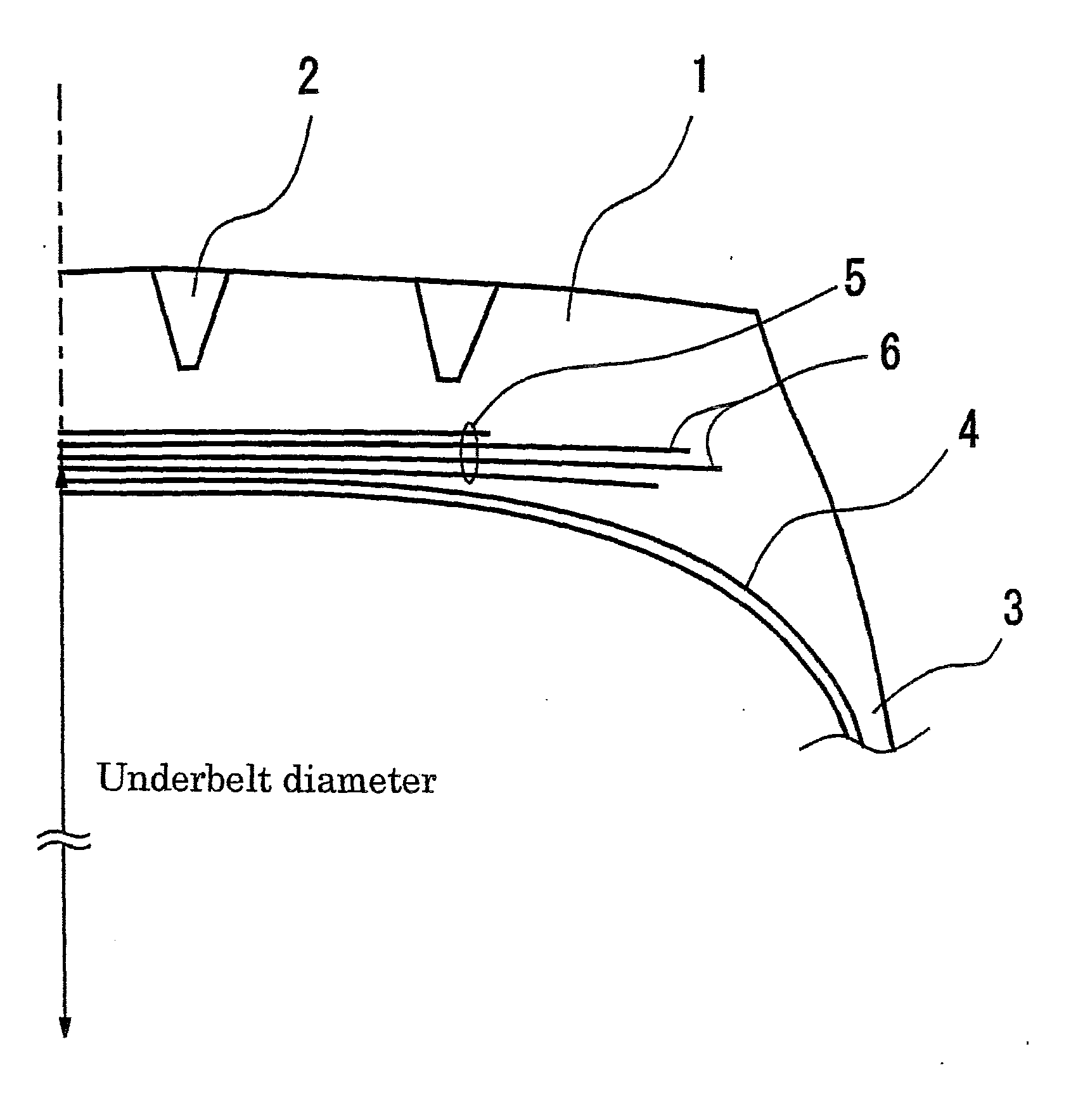
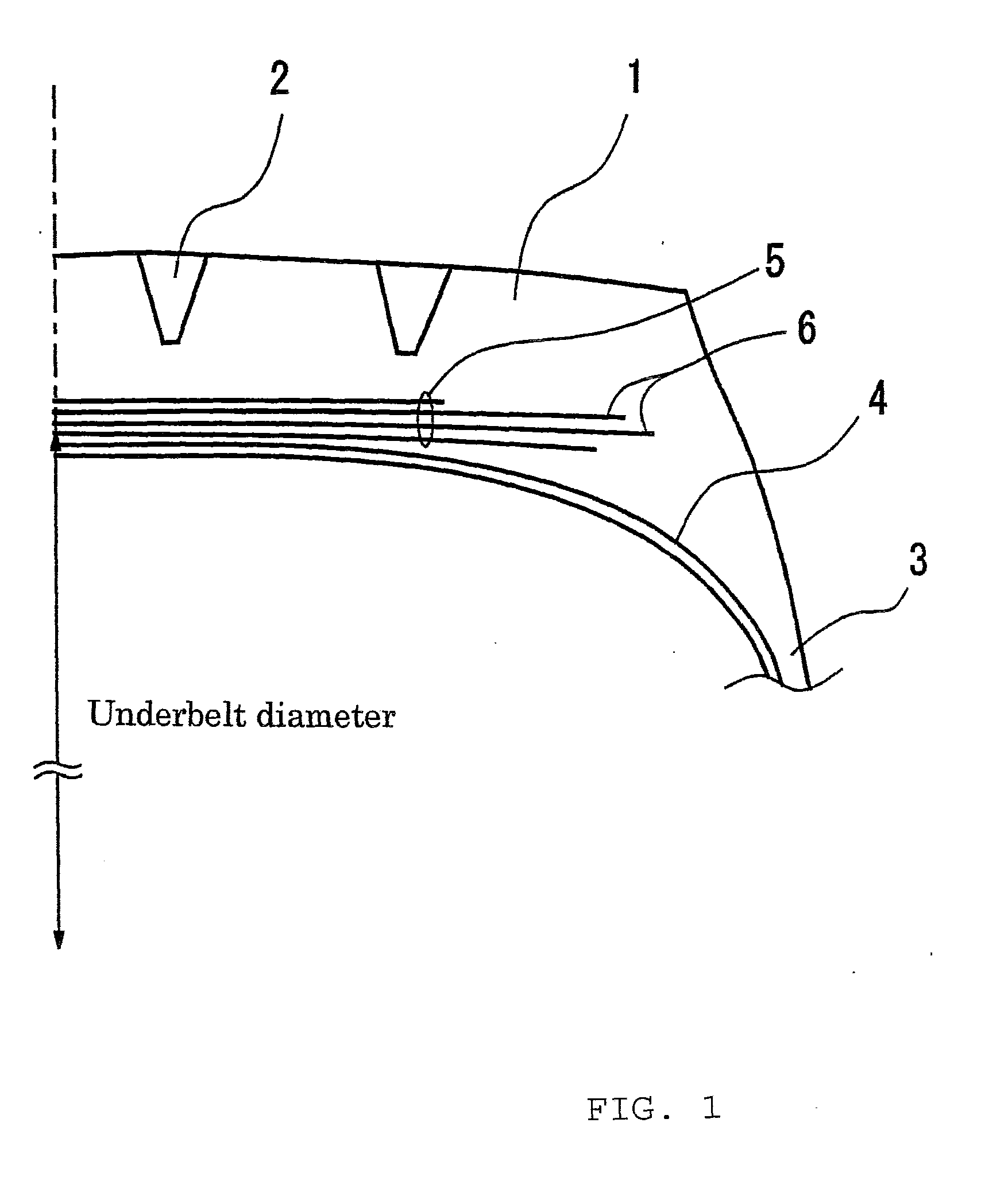
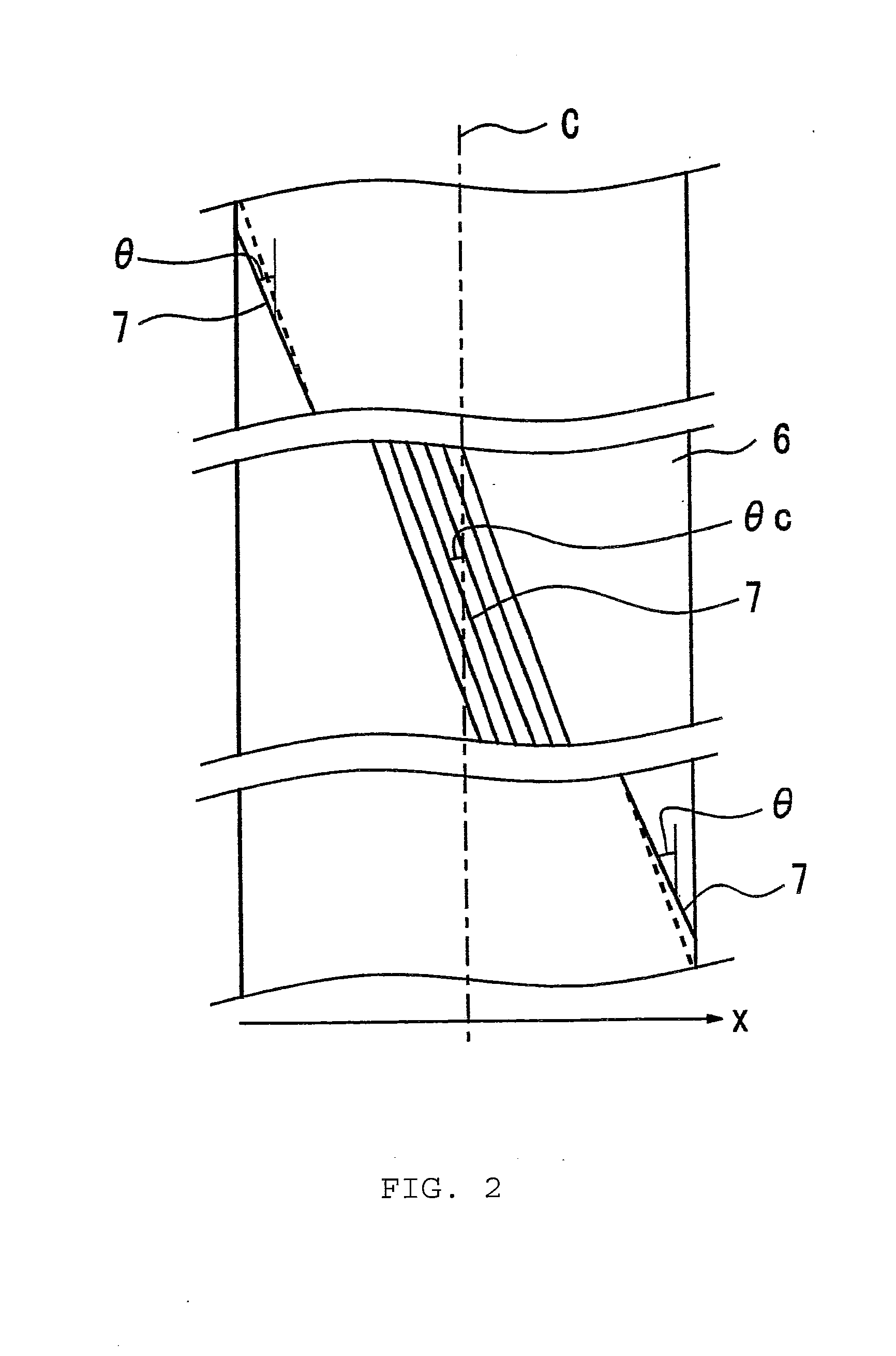
[0052]Tires for Examples and Conventional Examples were manufactured experimentally by die molds composed of 10 sector molds and a pair of side plates, and the angle deviation of steel cords were measured. The tire size was 11R22.5 and the results are shown in FIG. 6. In the figures, the changes in the underbelt diameter (L2 / L1−1) in Examples 1 and 2 and Conventional Example 1 were 0.0, 0.02, and 0.04, respectively. According to this, by making the changes in the underbelt diameter (L2 / L1−1) not greater than 0.02, the angle deviation could be inhibited to not greater than 3 degrees.

example 2

[0053]Tires of Example 1 and the Conventional Example 1 were installed on a truck with a load capacity of 10 tons and the growth amount of an inner surface of the tire after driving 20,000 km was measured. The result is shown in FIG. 7. According to this, in the tire of the present invention, the shape changes in accordance with the increase in driving distance are found to be small. In addition, the growth amount of an inner surface means to be the amount of shape changes in the diameter direction with time passage generated by driving.

example 3

[0054]Further, tires for Example 3 and Conventional Example 2 were manufactured experimentally and the durability of a belt was evaluated. The result is shown in Table 1. For information, the durability of the belt is a driving distance until the tire fails after drum-traveling based on the durability testing of ECE54 is conducted. The result is shown by indices making the value obtained in Conventional Example 1 100.

TABLE 1ComparativeComparativeExample 1Example 2Example 1Example 3Example 2Tire size11R22.511R22.511R22.5275 / 70R22.5275 / 70R22.5Changes in the underbelt0.00.020.040.00.03diameter (L2 / L1 − 1)Maximum angle deviation1.02.54.01.04.0(degree)Durability of a belt130110100150100


PUM

PropertyMeasurementUnit
angleaaaaaaaaaa
thicknessaaaaaaaaaa
angle deviationaaaaaaaaaa

Abstract

A pneumatic tire provided with a pair of bead cores, a troidal-shaped carcass surrounding said bead cores, a tread rubber, a carcass, a plurality of belt layers reinforced by steel cords, wherein in at least one of said belt layers, the maximum value of deviation of an angle θc of said steel cords is not greater than 3 degrees with respect to the angle made by said steel cords at the center in the tire width direction and the tire circumferential direction.

Description

CROSS REFERENCE TO RELATED APPLICATIONS[0001]This application is a division of co-pending U.S. application Ser. No. 11 / 708,407 filed Feb. 20, 2007, which claims priority benefits based on Japanese Patent Application No. 2006-044677, both of which are incorporated herein by reference in their entireties.BACKGROUND OF THE INVENTION[0002]1. Field of the Invention[0003]The present invention relates to a pneumatic tire, and in more detail, it relates to a method for manufacturing a pneumatic tire with improved durability by preventing angle deviation of steel cords in belt layers at the time of vulcanization molding.[0004]2. Description of Related Art[0005]In vulcanization molding of a tire, the difference between an underbelt diameter of a green tire and that of a vulcanized tire used to be large. As a result, angle deviation of steel cords in belt layers occurred, causing deterioration in durability of the belt layers. A manufacturing method disclosed in the patent document 1 (Japanese...

Claims


Application Information

Patent Timeline
Patent Type & Authority Applications(United States)
IPC IPC(8): B29D30/08
CPCB29D30/0629B29D2030/0631Y10T152/10765B60C9/28B60C9/2006B60C2009/2025
Inventor KASHIHARA, NAOTO
Owner TOYO TIRE & RUBBER CO LTD
Learn More