
Method of marking a document or item; method and device for identifying the marked document or item; use of circular polarizing particles

a document or item identification and marking technology, applied in the field of marking and identifying a document or item, to achieve the effect of high durability/stability of the marking

Active Publication Date: 2010-08-12
SICPA HLDG SA
View PDF43 Cites 67 Cited by
  • Summary
  • Abstract
  • Description
  • Claims
  • Application Information

AI Technical Summary

Benefits of technology

[0038]In particular, use is made of marking particles having the property of reflecting circular polarized light, in conjunction with corresponding authenticating equipment. This allows an easy distinguishing of the marking on almost all backgrounds, even if the latter is colored and / or reflective. The marking according to the invention is practicable on most materials and substrates, such as paper, plastics, metal, glass, printed items, etc.
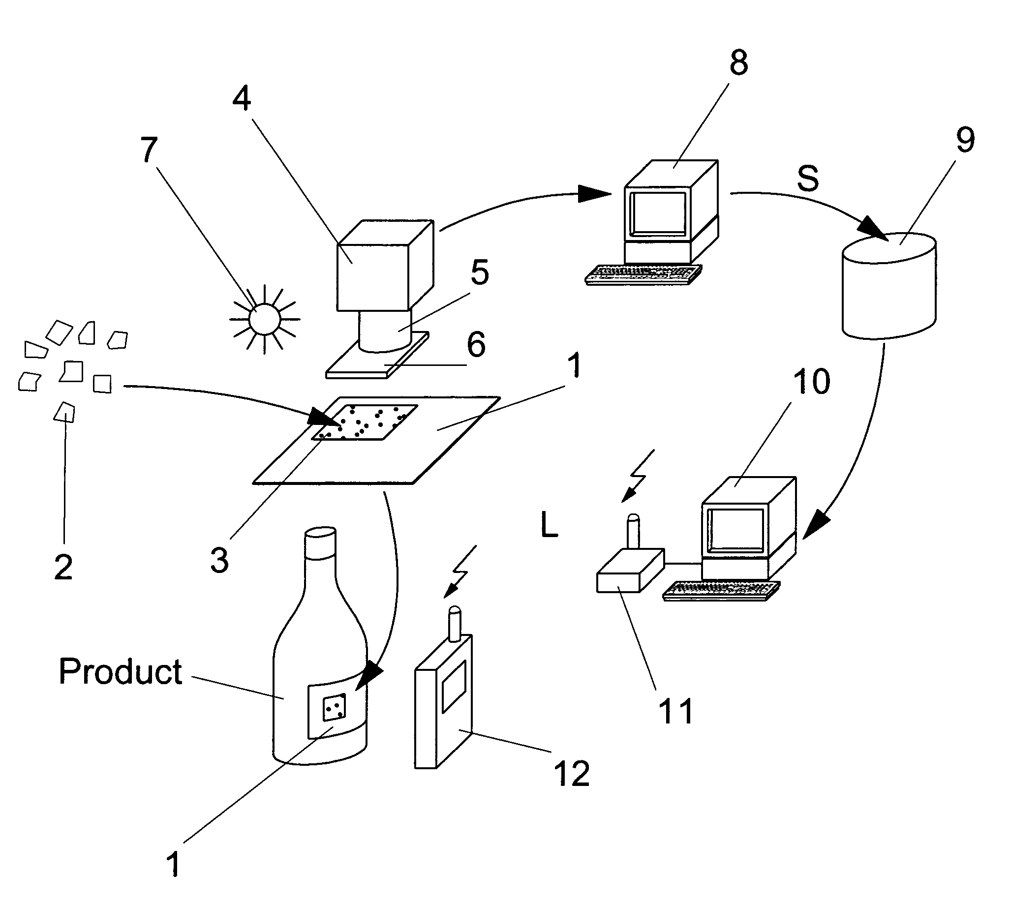
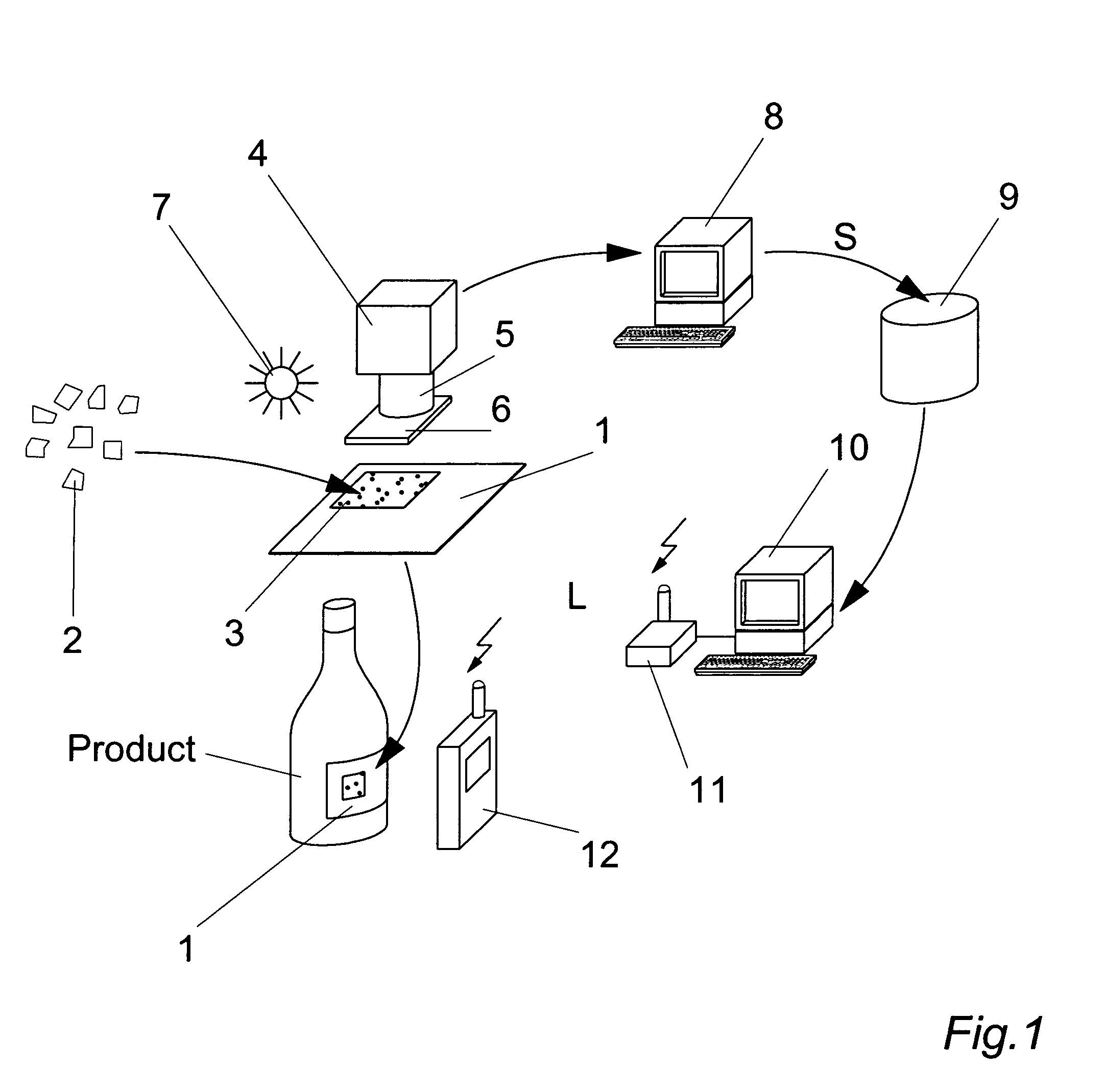
[0155]A document or item is authenticated or identified by the comparison of the retrieved data about the flake positions, orientations, color, color-shift, etc. in the marking area of the document or item with the “signature” of the original document or item, which has been previously stored in a database. An indexed or a raw data base may be used. Indexed data bases have the advantage of allowing for a rapid, content-driven search and access of the information.

Problems solved by technology

However, said contact between the item and the authenticating device may easily lead to a jamming of the item, in particular if the item to be authenticated is made of paper and is in a bad shape.
This is a particular disadvantage in case of banknote accepting ATMs (Automated Teller Machines) or AVMs (Automated Vending Machines) because multiple service intervention may be required.
The practical implementation of such identification, requiring a microscope and a very precise positioning, may, however, not be feasible outside a laboratory.
These luminescent particles, having a roughly spherical shape, cannot be used in the most common printing processes, such as offset, heliography and flexography printing due to their excessive 3-dimensional size.
Luminescence signals are generally weak, due to the intrinsic low efficiency of the luminescence energy conversion process, which is a significant obstacle to high speed authentication, such as often required in banknote processing.
The reflective particles are small and the resulting optical random pattern is extremely complex, providing a system that is highly robust against physical reconstruction.
A disadvantage of the method of authentication / identification of WO 02 / 50790 is the large number of particles present in the identification zone of the tagged item, requiring some sort of selection to be effectuated on the raw data before the particle distribution can be compared with the stored reference data (e.g. image enhancement processing according to FIG. 2 of the cited document).
Also, determining the orientation of the flakes requires complex reading equipment; furthermore, the said orientation of the flakes in the coating can change with time, under mechanical or chemical influences (crumpling, wetting, etc.).
Despite the many methods, markings, authentication equipment and systems disclosed in the prior art, which all make use of a random particle distribution as an identification means for documents or items, none of them has resulted in a large scale application.
The reasons for this are one or more of the following:a) The required contact of the reader device with the document or item in case of magnetic marking particles, which potentially leads to jamming;b) The small detection area, which is difficult to find and to focus correctly on the document or item;c) The required use of coarse-grain particles, hardly compatible with common printing techniques in case of luminescent markers;d) The large or even excessive quantity of position- and orientation-information of particles to be handled; which requires either an important data base and very performing search algorithms, or a pre-selection of a part of the marking particles to be effectuated;e) The time-consuming processing operations originated by the occurrence of one or more of the preceding points;f) The low resistance of the marking to mechanical or chemical damage;

Method used


Image

  • Method of marking a document or item; method and device for identifying the marked document or item; use of circular polarizing particles
  • Method of marking a document or item; method and device for identifying the marked document or item; use of circular polarizing particles
  • Method of marking a document or item; method and device for identifying the marked document or item; use of circular polarizing particles

Examples


Embodiment Construction

[0050]The method of marking and identifying or authenticating an item according to the present invention comprises the steps of a) providing an item, such as banknote, a voucher, an ID-document, a plastic card, a stamp, a label, a packaging, a good, etc. with a random distribution of particles, said particles being chosen as cholesteric liquid crystal polymer (CLCP) flakes; b) recording and storing, at a first point in time, data representative of said random distribution of flakes, using a reading device comprising illumination means and optical detection means; c) identifying or authenticating the marked item at a later point in time using a reading device as in step b) and said stored data representative of said random distribution of particles. The reading devices of step b) and c) need not to be the same, nor of the same type.

[0051]The term “reading device” designates a device which is capable to identify or to authenticate a document or item marked according to the present inv...


PUM


Abstract

Optical identification and / or authentication of a document or item with the help of a marking comprising a random distribution of circular polarized light reflecting particles, the marking being applied to the document or item through an ink, and the reading device exploiting circular polarization to discriminate the flakes from the background.

Description

FIELD OF INVENTION[0001]The invention is in the field of marking and identifying a document or item. It concerns a method for providing a document or an item with a unique, individual mark; a method and a device of identifying the marked document or item; as well as the use of circular polarizing particles to produce a unique, individual mark.STATE OF THE ART[0002]In the field of value document certification or identity control, the recognition of an individual document or item among a large quantity of similar items, i.e. the identification of the item, is often required. Identification is recognizing something or someone as a specific individual. Other times, only a certification of the object's genuineness, i.e. authentication is required. Authentication is establishing or confirming something or someone as belonging to a certain class. Note that if identity is ascertained, the item is authentic. The reverse is not true.[0003]A number of different solutions for identifying or aut...

Claims


Application Information

Patent Timeline
IPC IPC(8): G06K7/12G06F17/00G06K7/10
CPCG06K19/086G07D7/0046G02F1/133528G07D7/124G07D7/20G07D7/12G07D7/003G07D7/005G06F17/00G06K19/00
Inventor CALLEGARI, ANDREADECOUX, ERIC
Owner SICPA HLDG SA
Learn More