
Three dimensional motor generator system

a generator system and three-dimensional technology, applied in the direction of mechanical energy handling, electric generator control, mechanical equipment, etc., can solve the problems of inability to meet the increasing demand of power supply, and discomfort for users

Inactive Publication Date: 2010-08-12
DAHLEN HERBERT CAREY
View PDF20 Cites 5 Cited by
  • Summary
  • Abstract
  • Description
  • Claims
  • Application Information

AI Technical Summary

Benefits of technology

[0009]Another objective of the present invention is to provide a power supply system that extends the normal life cycle of batteries to provide the sustained power level for longer periods of time.
[0010]Another objective of the present invention is to provide a power supply system which reduces / eliminates the requirement of frequent recharging of batteries associated with laptops, PDA, toys, phones and other devices.
[0013]Another objective of the present invention is to provide a power supply system that generates power with minimal energy losses and required less amount of maintenance.
[0014]A further objective of the present invention is to provide a power supply system that is environmentally friendly, safe, and has decreased carbon emission.
[0015]Yet another objective of the present invention is to provide a power supply system whose scale and size can be increased or decreased depending on the application and power demand.
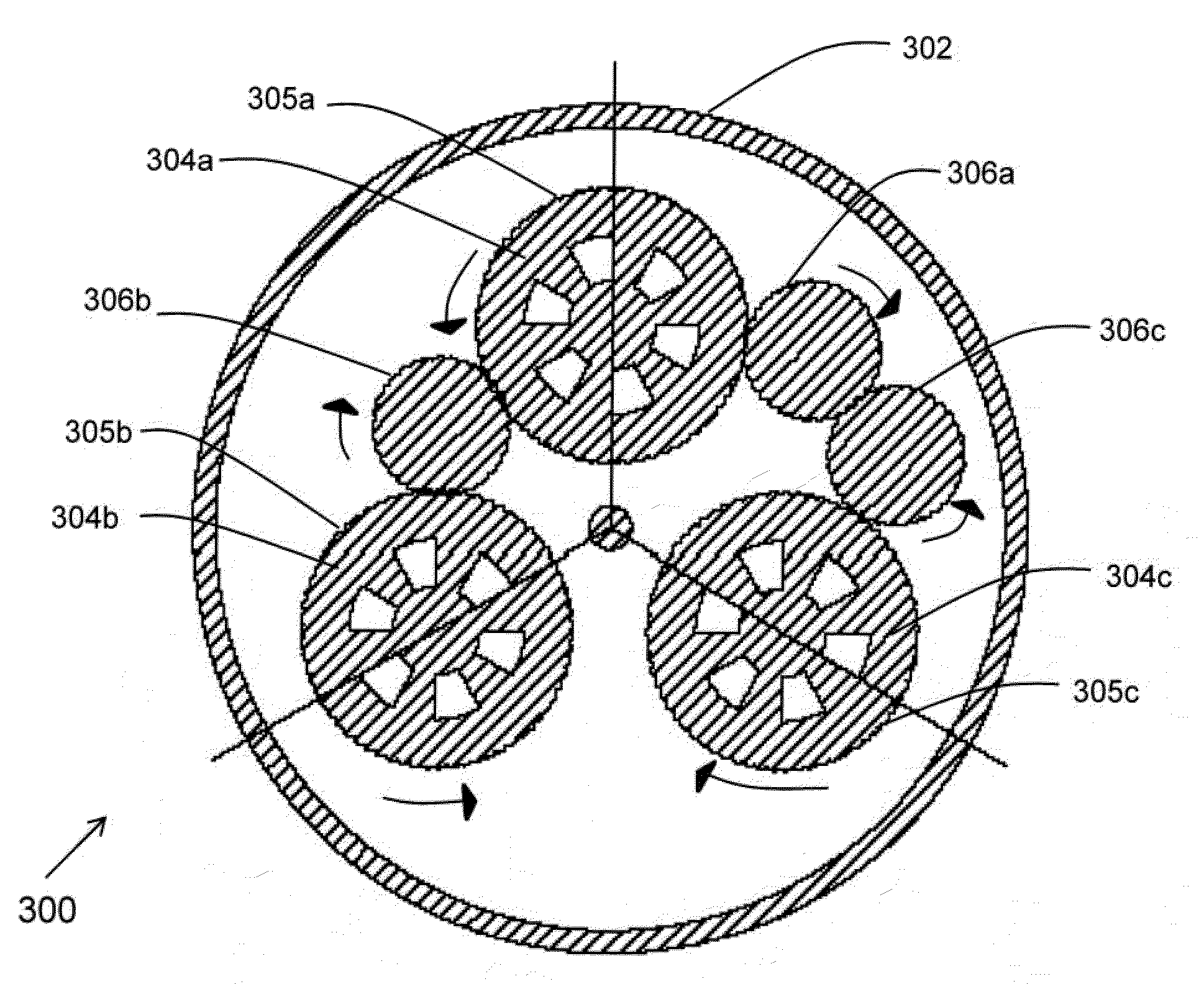
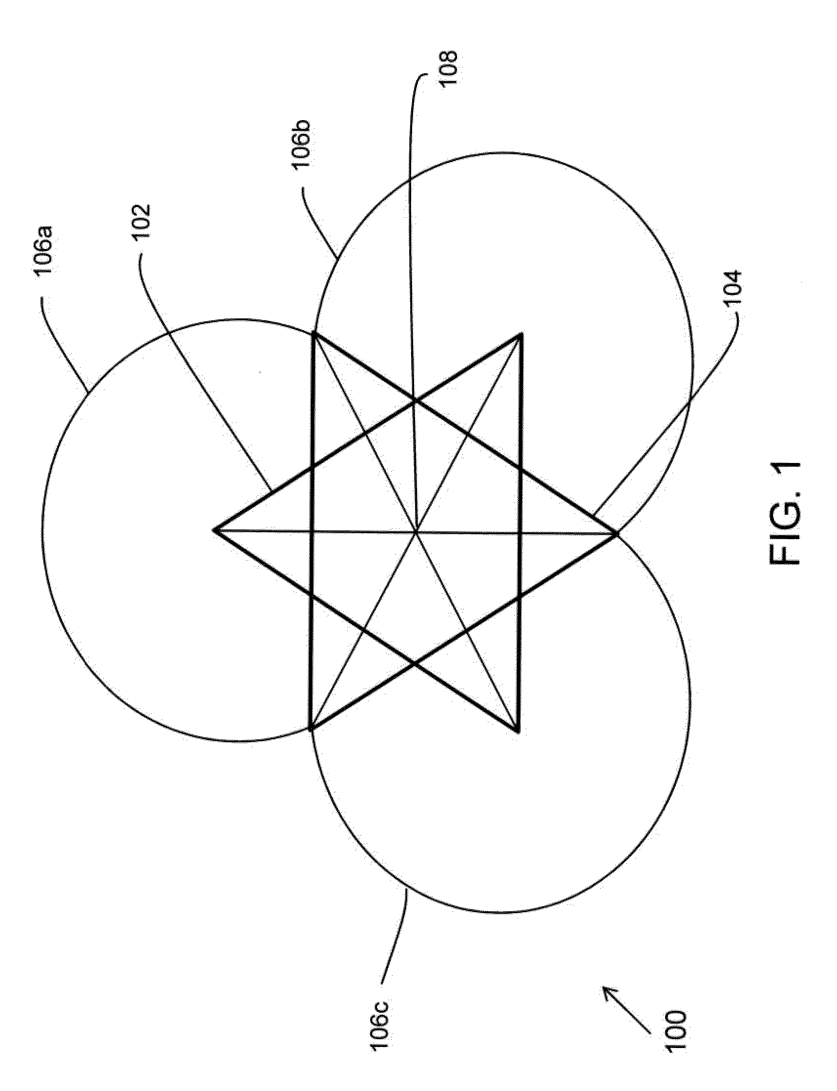
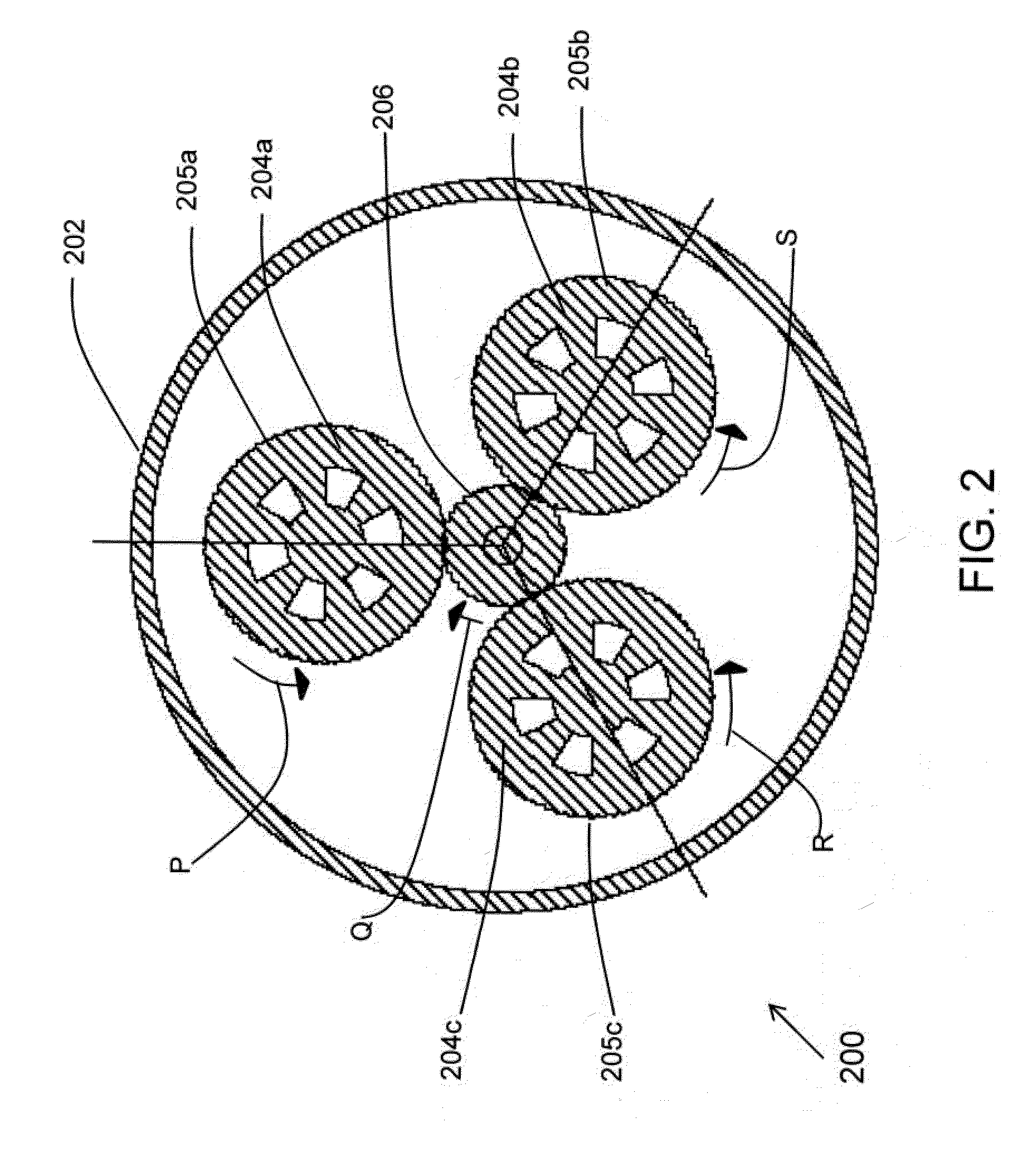
[0016]Embodiments of the present invention provide a universal three dimensional power supply system capable of compounding and multiplying the order of voltage or potential to or from a machine. Three rotors with permanent magnets and / or coil windings are mechanically interconnected through a gear arrangement and placed within the housing. Stator wraps around the rotors. Three rotors, stator and three coils are strategically positioned at six equidistance positions forming the hexagram points or resemble the “Star of David” configuration placed within a circular housing with one independent coil located in the exact center. The system allows multiple wiring configurations allowing each section of a rotor and stator configuration to operate independently or separately as a motor or generator, or in combination.

Problems solved by technology

One of the common problems that exist with the present-day electric motor / generator technology is the inability to meet the increasing demand of power supply.
The inability of power suppliers to meet the power demands causes discomfort to the user and decreases industrial output.
Most of the electric power plant systems and national electrical power grid systems suffer from one or more deficiencies which limits their effectiveness to meet the increasing demand of power supply.
One of the common problems is the need to regularly shut down power plants to replace / repair the insulation winding to avoid insulation breakdown which is very expensive and time consuming process.
However, such steps have become explosive over time, which can lead to the accidental hazards or destroy equipments or can burn or kill electricians.
This gave rise to higher cost of personal protective equipment and sometimes even extend the down time operation of power plants.
Such systems have failed to provide adequate power to keep pace with the increasing power requirement.
Prior art battery technology is facing several problems to supply power to small items like laptops, PDA, toys and the like.
One of the common problems with existing batteries is that they require frequent recharging to continue supplying the power.
At the same time the manufacturing industry has not been able to keep an affordable pace with the demand due to high costs and small life of batteries.
Batteries used in electrical vehicle propulsion systems fail to provide efficient power because of less supply of power output level and its frequent recharging problem.
This has led to the increased usage of internal combustion engines in automotive industry which operate using fossil fuels and cause damage to the environment.

Method used


Image

  • Three dimensional motor generator system
  • Three dimensional motor generator system
  • Three dimensional motor generator system

Examples


Embodiment Construction

[0026]Embodiments of the present invention provide a three dimensional motor generator system for compounding and multiplying the order of voltage / potential to or from a machine employing the permanent magnets and / or coil windings (hereafter referred as: windings) on rotors and stator. The following detailed description is merely exemplary in nature and is not intended to limit the described embodiments or the application and uses of the described embodiments. As used herein, the word “exemplary” or “illustrative” means “serving as an example, instance, or illustration.” Any implementation described herein as “exemplary” or “illustrative” is not necessarily to be construed as preferred or advantageous over other implementations. All of the implementations described below are exemplary implementations provided to enable persons skilled in the art to practice the disclosure and are not intended to limit the scope of the claims. Furthermore, there is no intention to be bound by any exp...


PUM


Abstract

A universal three dimensional motor generator system is provided with magnets and permanent magnetic and / or electromagnetic windings on rotors and stator for compounding and multiplying the order of voltage or potential to or from a machine. Three rotating rotors mechanically interconnected through gears and coils are strategically positioned within a housing that allows the multiple input and / or output of single and / or three phases A / C, D / C or in combination. When input power is supplied to rotor one, rotor two and rotor three start rotating along with rotor one due to gear arrangement to generate / produce power which is fed back to rotor one. This generated / produced power can / will be utilize to supplement the input power to maintain the synchronous speed across the designed load or combined to increase the output rating of machine. The system allows multiple wiring configurations allowing each section of a rotor and stator configuration to operate independently or separately as a motor or generator, or in combination.

Description

CROSS-REFERENCE TO RELATED APPLICATIONS[0001]This application claims the benefit of and incorporates by reference in its entirety U.S. provisional application No. 61 / 175,504, filed May 5, 2009 and entitled “Universal Three Dimensional Power Supply”.FIELD OF THE INVENTION[0002]The present invention relates to a three dimensional motor generator system. More particularly, it relates to an electric motor / generator system provided with permanent magnets and / or coil windings on rotors and stator for compounding and multiplying the order of voltage / potential to or from a machine.BACKGROUND[0003]Electric motors / generators are commonly used to supply power to various different size electrical products and applications. One of the common problems that exist with the present-day electric motor / generator technology is the inability to meet the increasing demand of power supply. The demand of electric power has increased manifolds due to high usage of electrical equipments and new constructions...

Claims


Application Information

Patent Timeline
IPC IPC(8): H02K7/20H02K53/00
CPCH02K53/00Y10S415/916
Inventor DAHLEN, HERBERT CAREY
Owner DAHLEN HERBERT CAREY
Learn More