Illuminating device and display device provided with the same

a technology of illumination device and display device, which is applied in the direction of lighting device details, lighting and heating apparatus, instruments, etc., can solve the problems of inability to completely prevent the contact between fluorescent tubes and lamp holders, the inability to completely prevent the temperature drop of the tube surface due to heat being transferred via the lamp holders, and the inability to produce luminance area reduction, etc., to achieve enhanced luminance uniformity of radiated light from a light-emitting surface, low power consumption, and reduced uneven luminance uneven lumina

Inactive Publication Date: 2010-08-12
SHARP KK
View PDF1 Cites 3 Cited by
  • Summary
  • Abstract
  • Description
  • Claims
  • Application Information

AI Technical Summary

Benefits of technology

[0019]According to a preferred embodiment of the present invention, an illuminating device in which the luminance uniformity of radiated light from a light-emitting surface is enhanced can be obtained as a large-area, thin edge-light illuminating device. Also, a thin, large-screen display device with low power consumption in which luminance unevenness on an image display surface is reduced to a level that a user is not able to perceive can be realized, by using the illuminating device according to a preferred embodiment of the present invention as a backlight of a display element that displays an image by controlling transmission of light.

Problems solved by technology

This problem of the tube surface temperature decreasing due to heat being transferred via the lamp holders cannot be completely prevented no matter how much the shape of the lamp holders is devised, given that contact between the fluorescent tubes and the lamp holders is unavoidable.
Then, there is a problem that occurs when the luminance of a fluorescent tube decreases at the portion contacting a lamp holder, whereby a decreased luminance area is produced in which the luminance on the light-emitting surface of the light-guiding plate decreases below the surrounding area, at least in proximity to that lamp holder portion.

Method used


Image

  • Illuminating device and display device provided with the same
  • Illuminating device and display device provided with the same
  • Illuminating device and display device provided with the same

Examples


first preferred embodiment

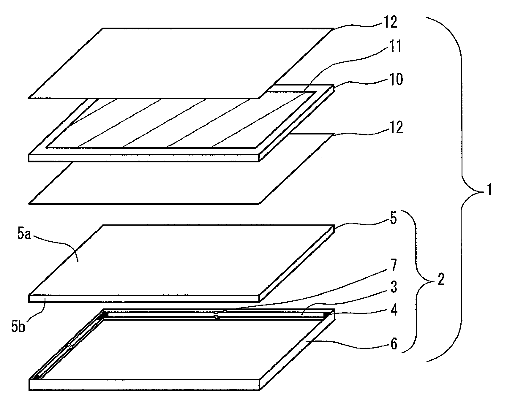
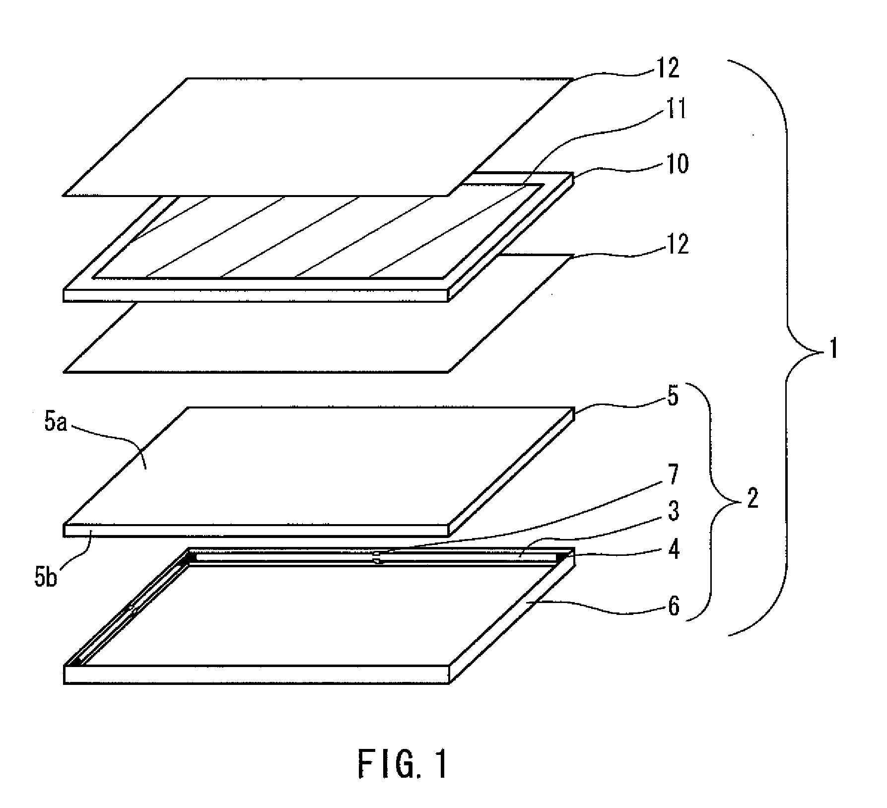
[0044]FIG. 1 is an exploded perspective view showing a schematic configuration of a display device according to a first preferred embodiment of the present invention. As shown in FIG. 1, a liquid crystal display device 1 according to a preferred embodiment of the present invention includes a liquid crystal panel 10 which is a display element and a backlight unit 2 which is an illuminating device that radiates transmission light necessary for performing image display in this liquid crystal panel 10.

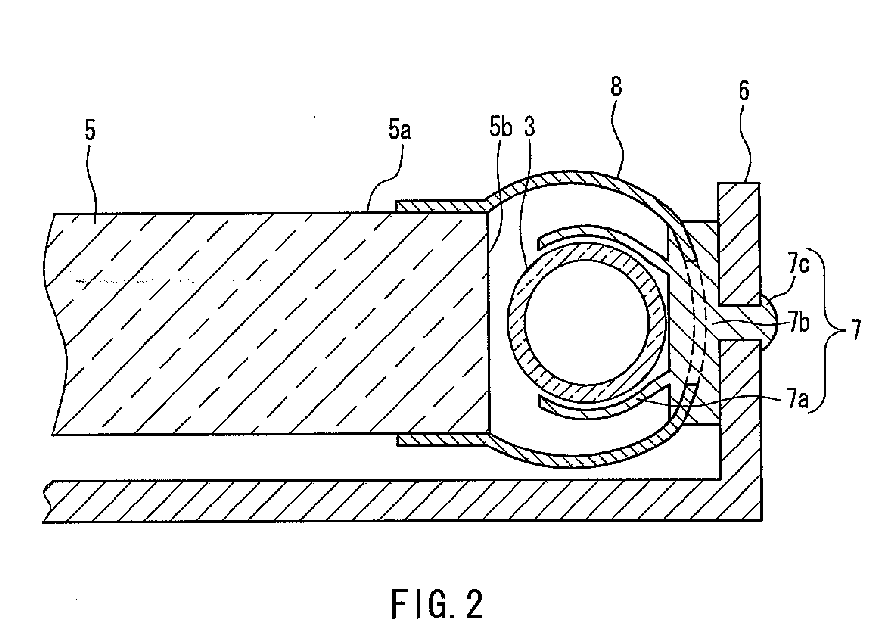
[0045]The backlight unit 2 includes a floored frame body 6, a plurality (e.g., four) of fluorescent tubes 3 (only two are visible in FIG. 1) which are tubular light sources respectively fixed to an inner surface of the four side walls of this frame body 6, and a light-guiding plate 5 which is light guide provided in a position such that lateral surfaces 5b thereof oppose these fluorescent tubes 3.

[0046]The fluorescent tubes 3 have a fluorescent substance that radiates white light applied i...

second preferred embodiment

[0076]A display device according to a second preferred embodiment of the present invention will be described hereinafter. Note that since the display device according to this second preferred embodiment only differs from the display device described in the first preferred embodiment with respect to a backlight unit 2 thereof, description of the overall configuration of the display device will be omitted. Repetitive description regarding the constituent elements described in the first preferred embodiment will also be omitted.

[0077]FIG. 6 shows a planar configuration of the backlight unit 2 of a liquid crystal display device 1 according to the second preferred embodiment of the present invention. As shown in FIG. 6, with the backlight unit 2 of the liquid crystal display device 1 according to the present preferred embodiment, two fluorescent tubes 3a and 3c that are only arranged so as to oppose the lateral surfaces of the longer sides of the light-guiding plate 5 constitute the fluo...

third preferred embodiment

[0082]Next, a display device according to a third preferred embodiment of the present invention will be described hereinafter. Note that since the display device according to this third preferred embodiment only differs from the display devices described in the first preferred embodiment and the second preferred embodiment with respect to a backlight unit 2 thereof, description of the overall configuration of the display device will be omitted. Repetitive description regarding the constituent elements described in the first preferred embodiment will also be omitted.

[0083]FIG. 7 shows a planar configuration of the backlight unit 2 of a liquid crystal display device 1 according to the third preferred embodiment of the present invention. As shown in FIG. 7, with the backlight unit 2 of the liquid crystal display device 1 according to the present preferred embodiment, the fact that two fluorescent tubes 3a and 3c disposed opposite the lateral surfaces of the longer sides of a light-guid...


PUM


Abstract

An illuminating device in which luminance unevenness caused by a lamp holder of a tubular light source is reduced is provided as a large-area, thin illuminating device formed as a surface-emitting light source by an edge light method, and a thin, large-screen display device with low power consumption that is able to obtain a display image quality that is not a problem on a practical level is provided, by using the illuminating device as a backlight of a display element that displays an image by controlling transmission of light. The illuminating device includes a tabular light guide including a light emitting surface that is preferably substantially rectangular, tubular light sources provided respectively opposite two opposing lateral surfaces of the light guide, and at least one pair of lamp holders respectively holding the tubular light sources at intermediate portions of two opposing lateral surfaces of the light guide, and the lamp holders in the pair are disposed so as to be displaced from each other in a tube axis direction of the tubular light sources.

Description

BACKGROUND OF THE INVENTION[0001]1. Field of the Invention[0002]The present invention relates to a so-called edge-light surface-emitting illuminating device that causes light from a tubular light source to be incident from a lateral surface of a light guide and irradiates this incident light from a light-emitting surface, and more particularly to a thin, large-area illuminating device capable of irradiating uniform light, and to a display device that uses light radiated from the illuminating device as light to be transmitted through a display element.[0003]2. Description of the Related Art[0004]In recent years, liquid crystal display devices having features such as low power consumption and being thin and lightweight have become widely used as liquid crystal display devices for televisions. A liquid crystal panel constituting a display element of a liquid crystal display device is a so-called non-emissive display element that does not emit light itself. Accordingly, an illuminating ...

Claims


Application Information

Patent Timeline
Patent Type & Authority Applications(United States)
IPC IPC(8): G09G3/36F21V7/04
CPCG02B6/009G02B6/0071
Inventor KAMADA, KENTARO
Owner SHARP KK
Why Eureka
Try Eureka