Touch screen with improved optical performace

a technology of optical performance and touch screen, applied in the field of touch screen, can solve the problems of reducing the visibility of space, achieve the effects of reducing the visibility of pattern, enhancing optical performance and aesthetic quality, and eliminating long spaces between electrodes

Inactive Publication Date: 2010-08-12
OCULAR LCD
View PDF11 Cites 26 Cited by
  • Summary
  • Abstract
  • Description
  • Claims
  • Application Information

AI Technical Summary

Benefits of technology

[0008]The application and claims herein are directed to an improved touch screen with enhanced optical performance and aesthetic quality. The sense electrodes and other traces on the touch screen are made less invisible to the user by substantially filling the space between the electrodes with isolated traces or regions that match the light transmission characteristics of the electrodes. In capacitive and resistive touch screens, the space between ITO electrodes and other traces on the substrate is substantially filled with ITO regions to match the electrodes. The space between electrodes is preferably filled with isolated regions of ITO formed in a geometric pattern. The isolated regions in the geometric pattern may be shaped to eliminate long lines of space to further reduce the visibility of the pattern. In addition, the edges of the electrodes may be notched and integrated with the geometric shapes to further eliminate long spaces between the electrodes. Further, the space between ITO traces can be filled with irregularly shaped ITO regions to further reduce the visibility of the space.

Problems solved by technology

Further, the space between ITO traces can be filled with irregularly shaped ITO regions to further reduce the visibility of the space.

Method used


Image

  • Touch screen with improved optical performace
  • Touch screen with improved optical performace
  • Touch screen with improved optical performace

Examples


Embodiment Construction

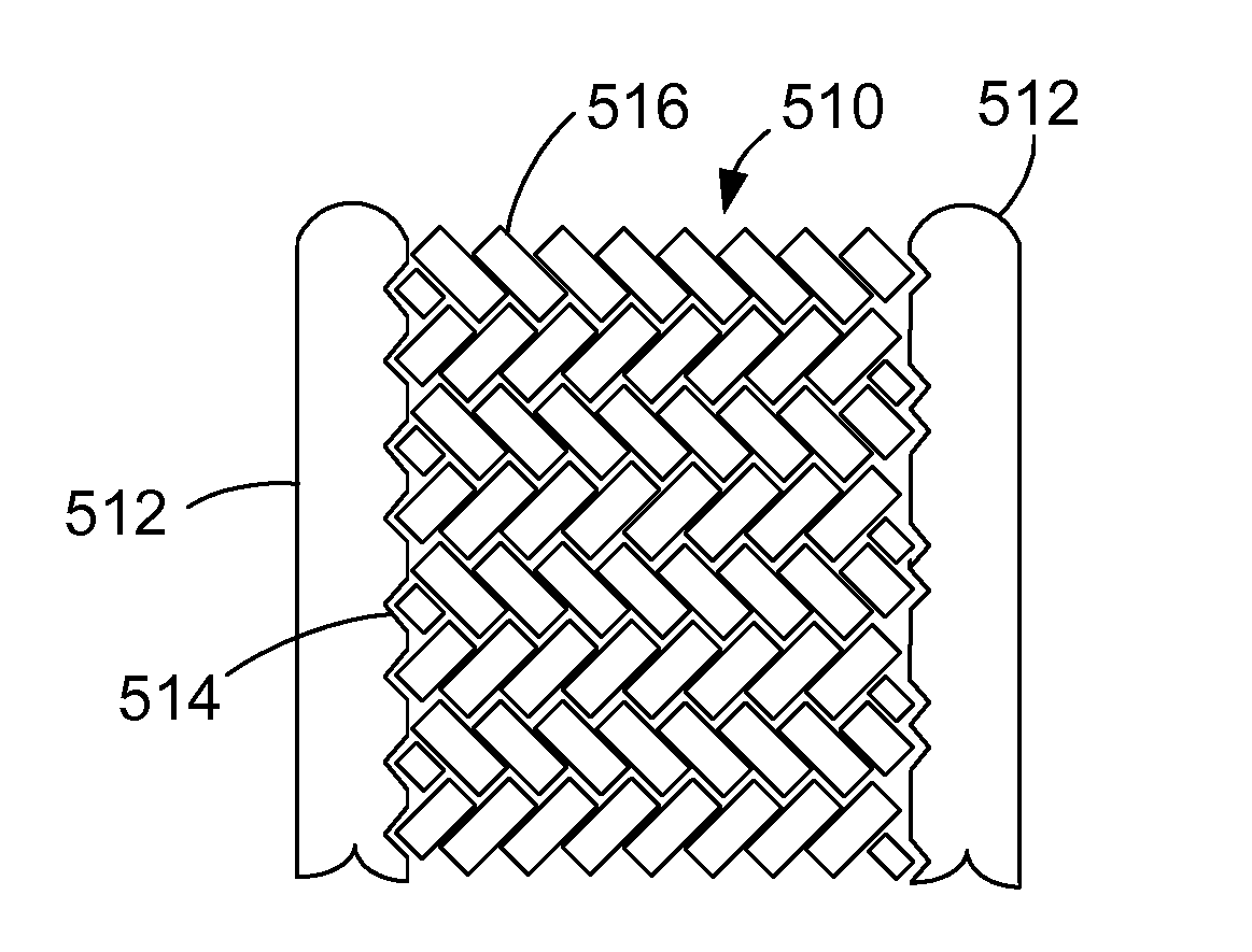
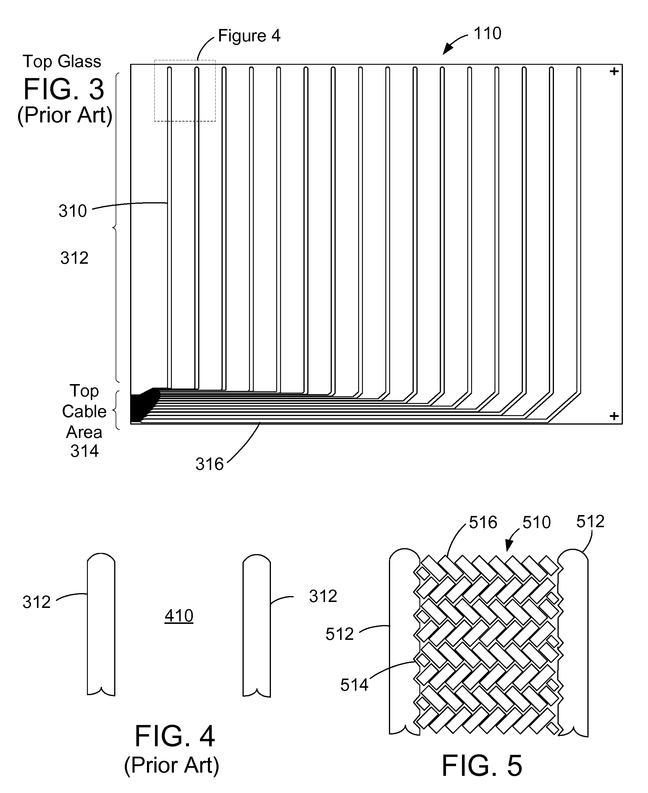
[0027]The description and claims herein are directed to an improved touch screen. The sense electrodes and other traces on the touch screen are made less invisible to the user by substantially filling the space between the traces with isolated regions of material that match the light transmission characteristics of the traces. In capacitive and resistive touch screens, the space between ITO electrodes and other traces on the substrate is substantially filled with ITO regions that match the optical characteristics of the electrodes.

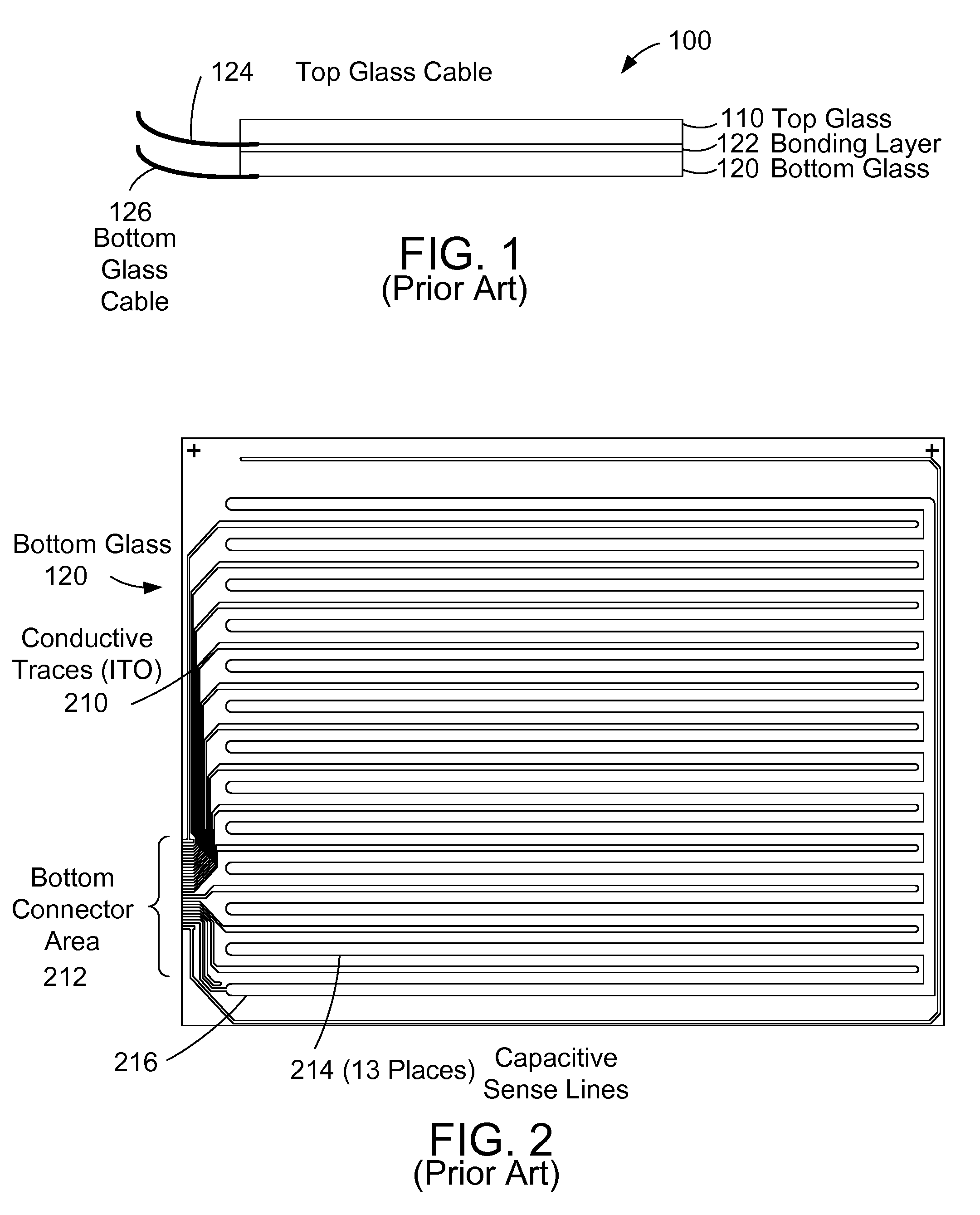
[0028]FIG. 1 shows a simplified side view of a capacitive touch screen 100 according to the prior art. The touch screen 100 has a top glass 110 and a bottom glass 120. The top glass 110 is bonded to the bottom glass 120 with a bonding layer 122. The top glass 110 has a top glass cable 124 that connects to conductive traces (not shown) on a portion of the bottom surface of the top glass 110. Similarly, bottom glass 120 has a bottom glass cable 126 that conn...


PUM


Abstract

An improved touch screen has enhanced optical performance and aesthetic quality. The sense electrodes and other traces on the touch screen are made less invisible to the user by substantially filling the space between the conductive traces or electrodes with isolated regions that match the light transmission characteristics of the electrodes. In capacitive and resistive touch screens, the space between ITO electrodes and other traces on the substrate is substantially filled with ITO to match the electrodes. The space between electrodes is preferably filled with isolated regions of ITO formed in a pattern. The isolated regions in the pattern may be shaped and the electrodes notched to create non-linear spaces to further reduce the visibility of the pattern. Further, the space between ITO traces can be filled with irregular-shaped ITO regions to further reduce the visibility of the space.

Description

BACKGROUND[0001]1. Technical Field[0002]The disclosure and claims herein generally relate to touch screens, and more specifically relate to a touch screen with improved optical performance by incorporating a fill pattern between the sense electrodes.[0003]2. Background Art[0004]Touch screens have become an increasingly important input device. Touch screens use a variety of different touch detection mechanisms. One important type of touch screen is the capacitive touch screen. Capacitive touch screens are manufactured via a multi-step process. In a typical touch screen process, a transparent conductive coating, such as indium tin oxide (ITO) is formed into conductive traces on two surfaces of glass. The conductive traces on the two surfaces of glass form a grid that can sense the change in capacitance when a user's finger or a pointer touches the screen. The published Patent Application No. 2008 / 0245582, filed Mar. 31, 2008 by Jared G. Bytheway, titled Floating Capacitive Couplers Us...

Claims


Application Information

Patent Timeline
Patent Type & Authority Applications(United States)
IPC IPC(8): G06F3/041
CPCG06F3/045G06F3/044G06F3/0445G06F3/0446
Inventor MOZDZYN, LARRY STEVENKWONG, BENEDICT
Owner OCULAR LCD
Why Eureka
Try Eureka