
Image Display System with Visual Server

a visual server and image display technology, applied in the field of computer systems, can solve the problems of requiring relatively limited client storage and processing capabilities, unable to provide true image generation services, and the most difficult rendering, so as to achieve the effect of being easily updated and maintained

Inactive Publication Date: 2010-08-12
INTELLECTUAL PIXELS
View PDF2 Cites 9 Cited by
  • Summary
  • Abstract
  • Description
  • Claims
  • Application Information

AI Technical Summary

Benefits of technology

Enables interactive generation and display of complex graphical images on client devices without requiring significant client resources, utilizing existing networking technology and allowing for easy maintenance and updates of the visual server without affecting client applications.

Problems solved by technology

Of these, rendering is the most difficult as it is the most processing intensive action.
In these systems, the client must be capable of rendering the complete replicated database in real time, and the server does not provide true image generation services.
Such method also requires relatively limited client storage and processing capabilities.
Moreover, since primitives visible in a current frame are likely to be visible in a subsequent frame, the repeated transmission of primitives that have been transformed to image-space representation is an inefficient use of available bandwidth.
Any processing to identify repetitive primitives requires further client resources, which hampers the image displaying process.
However, this method reduces communication cost by limiting transmission to those primitives that have become potentially visible.
The client replaces primitives in the client display list when they are no longer included in the spherical clipping volume, and thus, the storage and computing requirements of the client are limited to only those primitives in the potentially visible set.
However, as this method uses a limited inclusion volume, a major disadvantage is that distant primitives can be arbitrarily excluded from the potentially visible data set.
Further, the use of a spherical inclusion volume results in the inclusion and transmission of a large number of geometric primitives that are not visible in the current frame and are unlikely to be visible in upcoming frames, an example being primitives in the inclusion sphere behind the viewpoint.
As a result, the demand-driven geometry transmission makes inefficient use of available transmission bandwidth and available client storage and computing resources, and the client resources are taxed because the client must compute removal of primitives by clipping to the inclusion volume, and implement display list replacement and compaction protocols.
In existing clients, the implementation of a system delivering 3D graphics requires graphics hardware at the client, which presents several problems.
The additional hardware increases the cost of the client hardware as the graphics hardware must be incorporated and integrated therewith.
Further, the software and hardware used to generate 3D images is in constant flux, and the system must be continually upgraded, creating an additional expense and a logistical burden for the client.
Moreover, the remote hardware impedes the central maintenance and coordination of configurations of client software, which is an important capability and critical to the product viability of many applications.
Some clients use separate 3D hardware component to assist in processing the images, but with the constant change of graphics languages and protocols, the hardware becomes obsolete rather quickly, which adversely impacts the value of the client.
Furthermore, the use of programmable graphics hardware within the client system is difficult because the client resources are inherently static and limited.
Therefore, for reasons of cost, size, and power consumption, sophisticated three dimensional graphics are not available on common consumer client devices such as personal digital assistants (PDAs) mobile telephones and set-top boxes used to decode cable and satellite television signals.

Method used


Image

  • Image Display System with Visual Server
  • Image Display System with Visual Server
  • Image Display System with Visual Server

Examples


Embodiment Construction

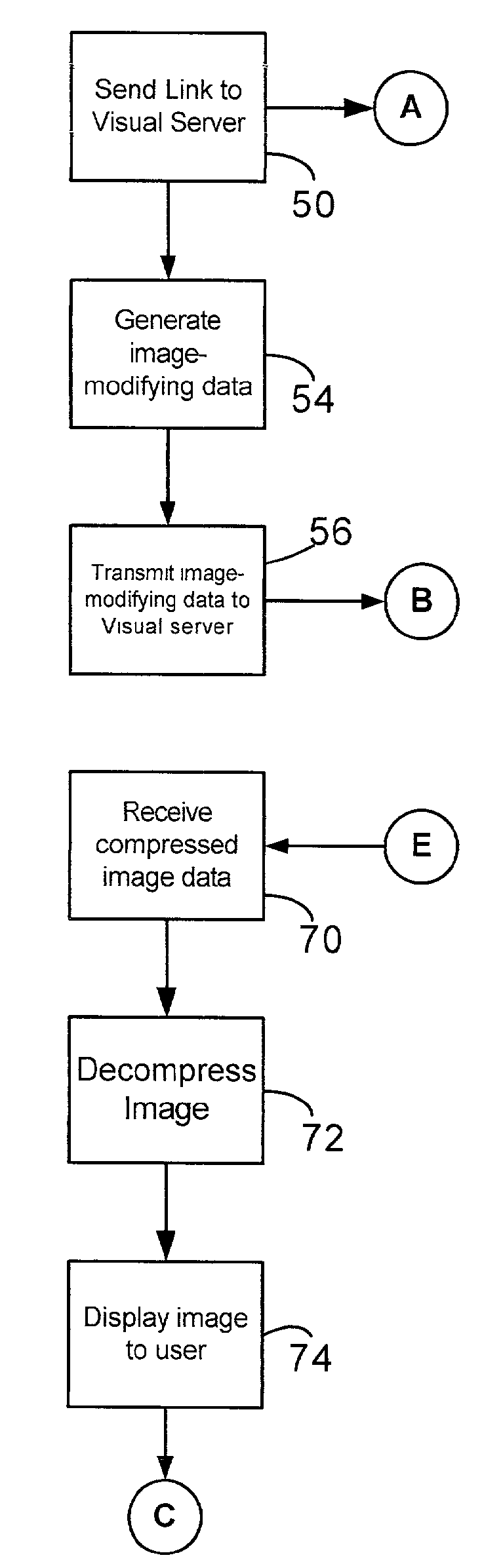
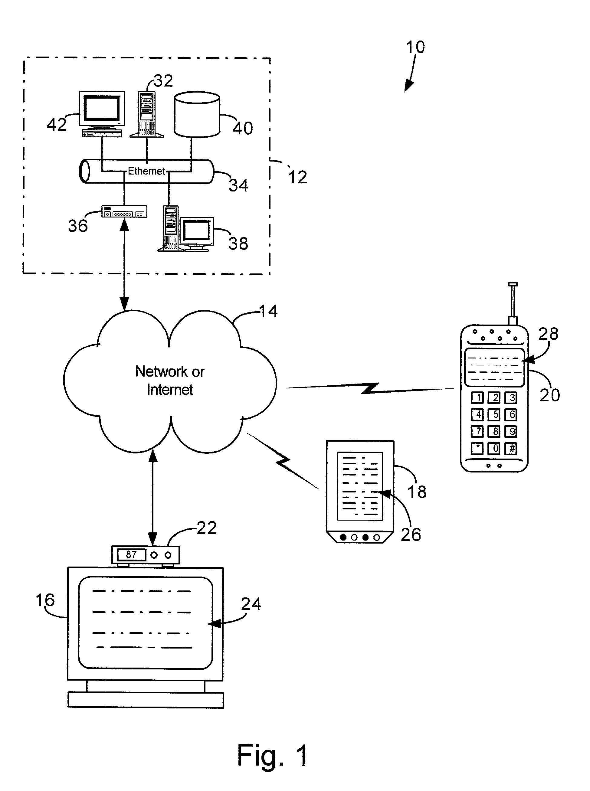
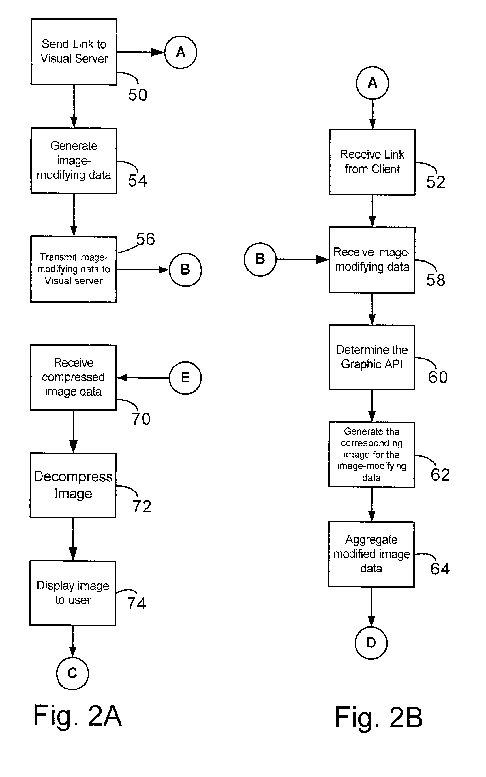
[0026]With reference to the figures in which like numerals represent like elements throughout, FIG. 1 is representational diagram of the image display system 10 with a visual server 12 and associated components in selective communication with a plurality of clients across a network 14, such as the Internet. The client components are shown as a television 16 having a set-top box 22 in communication with the network 14, and the set-top box 22 can selectively provide image data to the display 24 of the television 16. Set-top box 22 is similar to the type of boxes generally extant, except that the set-top box 22 in the present system must be able to receive and decompress compressed image data from the visual server 12. The same capability must be present in any client device in order to have the advantages of using the present system 10 for image data processing. Another exemplary clients are PDA 18, such as a Palm Pilot or a Handspring Visor, which has a display screen 26, and cellula...


PUM


Abstract

An image display system with one or more client computers in selective communication with a visual server having image processing capabilities. The client computer generates image modifying data corresponding to a generated image, and transmits the data to the visual server. The visual server receives the image-modifying data, generates a modified image based upon the image-modifying data, and transmits the modified image as compressed data to the client. The client decompresses the modified image data and displays the modified image. In the system, the visual server and client can provide a sequential display of modified frames on client to support animation with complex 3-dimensional graphics.

Description

CROSS-REFERENCE TO RELATED APPLICATION[0001]This application claims the benefit of U.S. Provisional Application Ser. No. 60 / 263,854, filed Jan. 24, 2001.BACKGROUND OF THE INVENTION[0002]1. Field of the Invention[0003]The present invention generally relates to computer systems. More particularly, the present invention relates to computer graphics and a graphical image display system that use a visual server to generate and transmit images to a client.[0004]2. Description of the Related Art[0005]Computer generated images are created in a series of several steps: modeling, or describing the objects in mathematical terms; animation, or describing how the objects move over time; and rendering, or determined which of the images defined by the modeling and animation programs are visible on the screen for every frame, assigning color to those images, and drawing them. Of these, rendering is the most difficult as it is the most processing intensive action. Because the generation of images is...

Claims


Application Information

Patent Timeline
Patent Type & Authority Applications(United States)
IPC IPC(8): G06F13/14
CPCG06T9/00G06T15/005A63F13/12H04L29/06047G06T2200/16H04L67/00A63F13/25H04L65/70
Inventor KENT, OSMANBALDWIN, DAVID R.MURPHY, NICHOLAS J.N.
Owner INTELLECTUAL PIXELS
Features
  • Generate Ideas
  • Intellectual Property
  • Life Sciences
  • Materials
  • Tech Scout
  • Unparalleled Data Quality
  • Higher Quality Content
  • 60% Fewer Hallucinations
Learn More