
Drive recorder, drive recorder system, method of controlling drive recorder, and program

a technology which is applied in the field of drive recorder and recorder system, and the method of controlling the drive recorder, can solve the problems of evidence data vanishing and movie image data vanishing, and achieve the effect of reducing the risk of losing evidence data

Inactive Publication Date: 2010-08-12
SEIKO EPSON CORP
View PDF6 Cites 37 Cited by
  • Summary
  • Abstract
  • Description
  • Claims
  • Application Information

AI Technical Summary

Benefits of technology

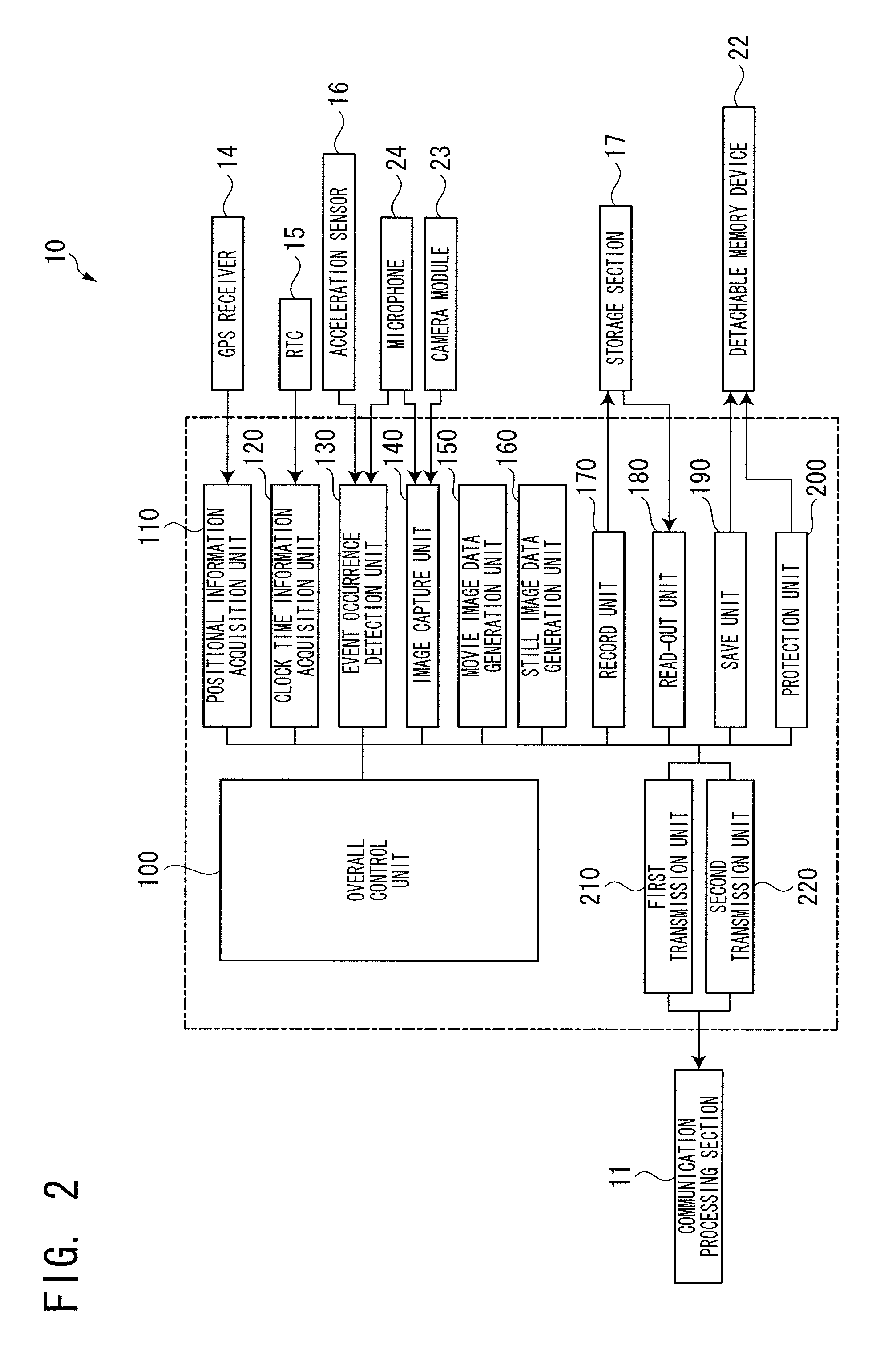
The patent text describes a drive recorder system that can reduce the risk of losing evidence data in the event of an accident. The system includes an image capture unit that captures images of the vehicle, a movie image data generation unit that stores the images as movie image data, an event occurrence detection unit that detects the occurrence of a predetermined event, a still image data generation unit that generates still images at predetermined intervals, and a transmission unit that sends the still image data and the movie image data to an external device. The system can also save the evidence data in a detachable memory device or in a way that ensures its preservation. The technical effect of the invention is to provide a reliable and effective means for recording and preserving evidence data in the event of an accident.

Problems solved by technology

In a case where a vehicle is burned in a large scale accident, an MRAM in such a drive recorder as described in the above patent document also gets burned so that a problem may arise in that the movie image data vanishes.
Namely, even when the movie image data is recorded as evidence data for determining a cause of an accident in the event of the accident, the evidence data may vanish due to the accident, which is like putting “the cart before the horse”.

Method used


Image

  • Drive recorder, drive recorder system, method of controlling drive recorder, and program
  • Drive recorder, drive recorder system, method of controlling drive recorder, and program
  • Drive recorder, drive recorder system, method of controlling drive recorder, and program

Examples


Embodiment Construction

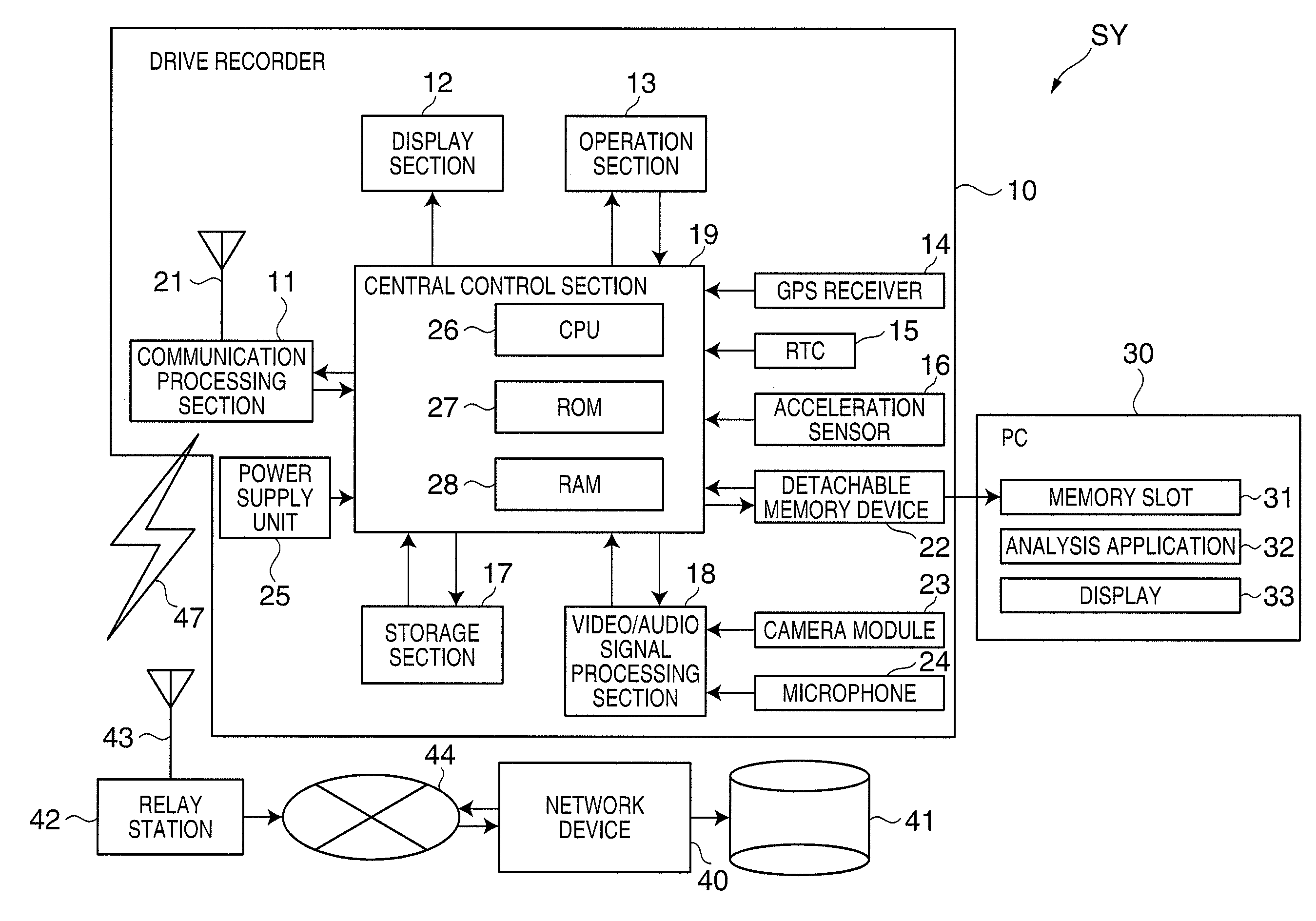
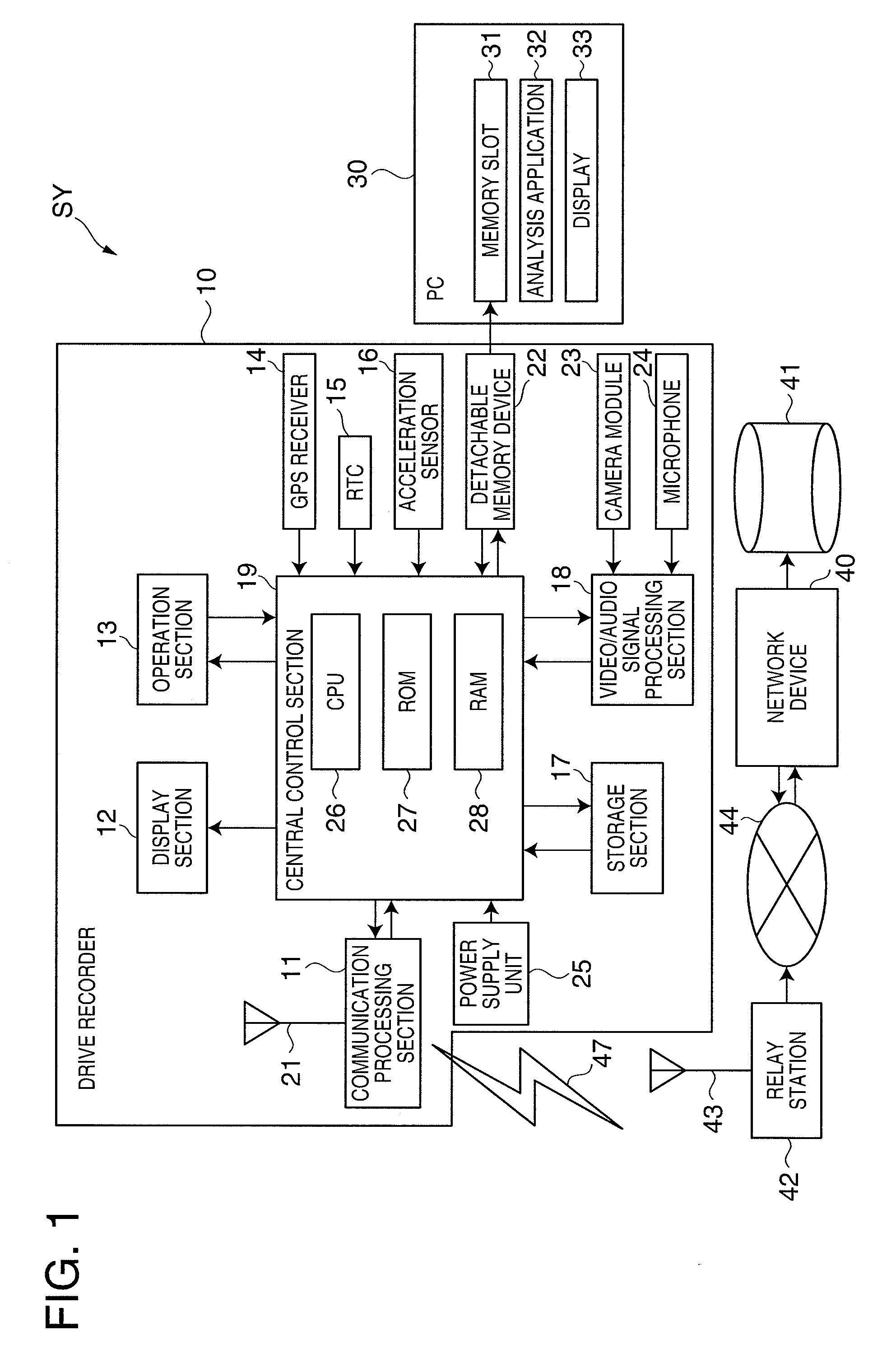
[0035]A drive recorder, a drive recorder system, a method for controlling the drive recorder and a program according to embodiments of the invention will be described with reference to the accompanying drawings. FIG. 1 is a system configuration diagram of a drive recorder system SY. As shown in FIG. 1, the drive recorder system SY includes a drive recorder 10 to be installed in a vehicle (an automobile) (not shown), a personal computer 30 (hereinafter, referred to as PC) for allowing a user as an owner of the drive recorder 10 to browse or listen to various kinds of data recorded in the drive recorder 10, and a network device 40 (an external device) for receiving and storing various kinds of data that is transmitted from the drive recorder 10.

[0036]The drive recorder 10 has a communication processing section 11, a display section 12, an operation section 13, a GPS (Global Positioning System) receiver 14, an RTC (Real Time Clock) 15, an acceleration sensor 16, a storage section 17, a...


PUM


Abstract

A drive recorder is provided that can reduce a risk of losing evidence data in the event of occurrence of an accident. The drive recorder includes an image capture unit that captures a front view of a vehicle in a traveling state, a movie image data generation unit that generates movie image data from a captured video signal, a storage section that stores movie image data, a recording unit that records movie image data into the storage section, an event occurrence detection unit that detects the occurrence of an accident, a still image data generation unit that generates still image data including a plurality of still images at predetermined intervals from the video signal, a first transmission unit that transmits still image data to an external device via a wireless network when the event occurrence detection unit detects the occurrence of an accident, and a second transmission unit that transmits the movie image data after the completion of the transmission by the first transmission unit.

Description

[0001]This application is a U.S. National Phase of PCT / JP2008 / 001787, filed Jul. 4, 2008, which claims priority to Japanese Patent Application No. 2007-197028, filed Jul. 30, 2007. The contents of all of the aforementioned applications are hereby incorporated by reference in their entirety.BACKGROUND OF THE INVENTION[0002]The present invention relates to a drive recorder that records movie image data of a portion inside or outside of a vehicle in a traveling state in order to record evidence data for determining a cause of an accident, a drive recorder system, a method of controlling a drive recorder, and a program.[0003]Heretofore, as such drive recorders, a drive recorder that stores movie image data in a nonvolatile memory such as an MRAM and turns on a save flag in accordance with a data save request due to detection of occurrence of an accident so as to prevent the movie image data from being erased when the accident occurs, has been known (e.g., see Japanese Unexamined Patent ...

Claims


Application Information

Patent Timeline
Patent Type & Authority Applications(United States)
IPC IPC(8): H04N7/18
CPCB62D41/00G07C5/008G07C5/0858G07C5/0866G07C5/0891H04N21/4334H04N5/23206H04N5/23245H04N5/76H04N21/41422H04N21/4223H04N5/232H04N23/661H04N23/667
Inventor MINOWA, MASAHIRO
Owner SEIKO EPSON CORP
Learn More