

Immersion type microscope objective lens
a technology of objective lens and microscope, which is applied in the field of objective lens used for immersion type microscope, can solve the problem of insufficient numerical aperture of the microscope, and achieve the effect of high numerical aperture and excellent correction of various aberrations in the broad wavelength rang
- Summary
- Abstract
- Description
- Claims
- Application Information
AI Technical Summary
Benefits of technology
Problems solved by technology
Method used
Image

Examples
example 1
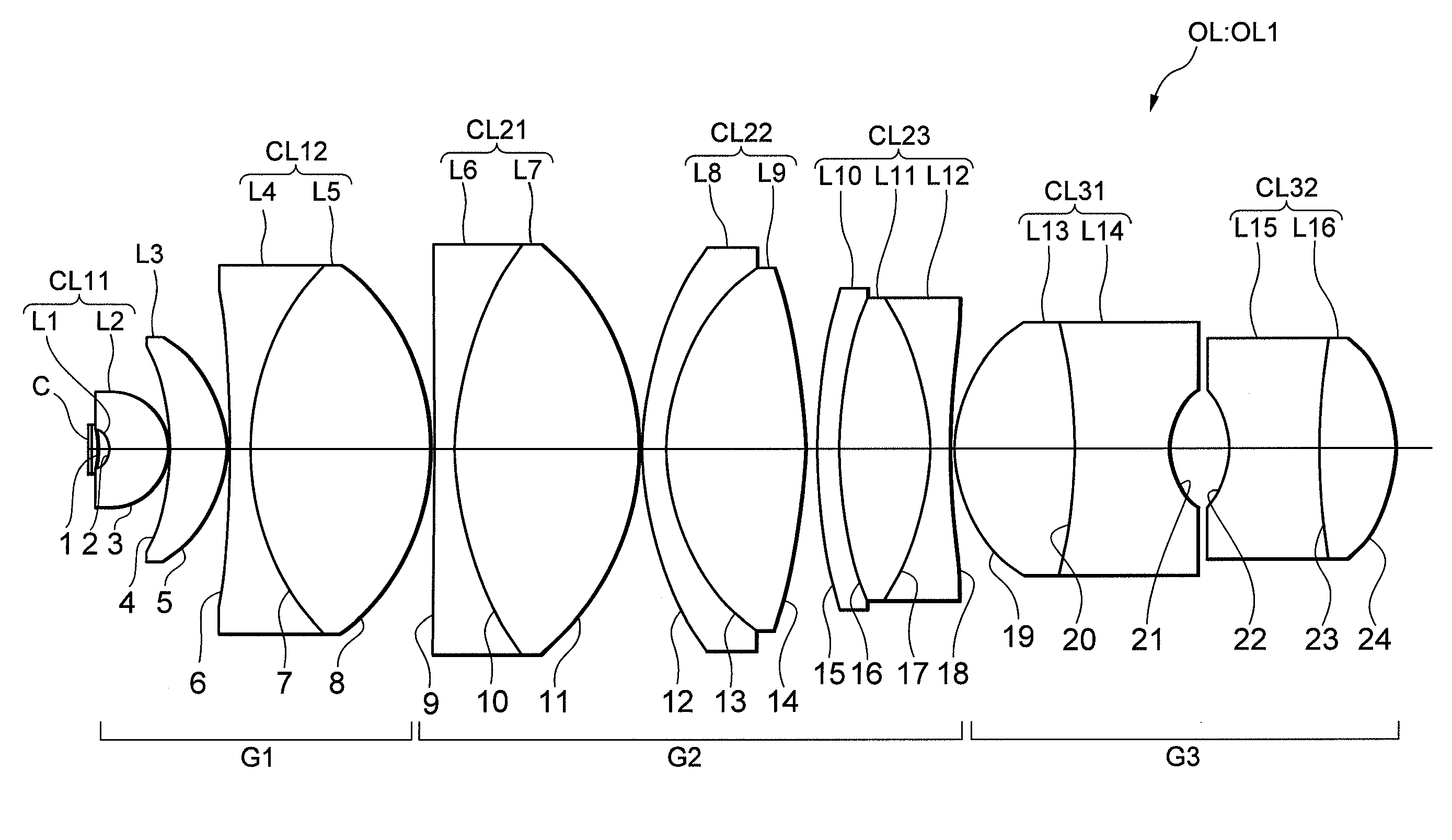
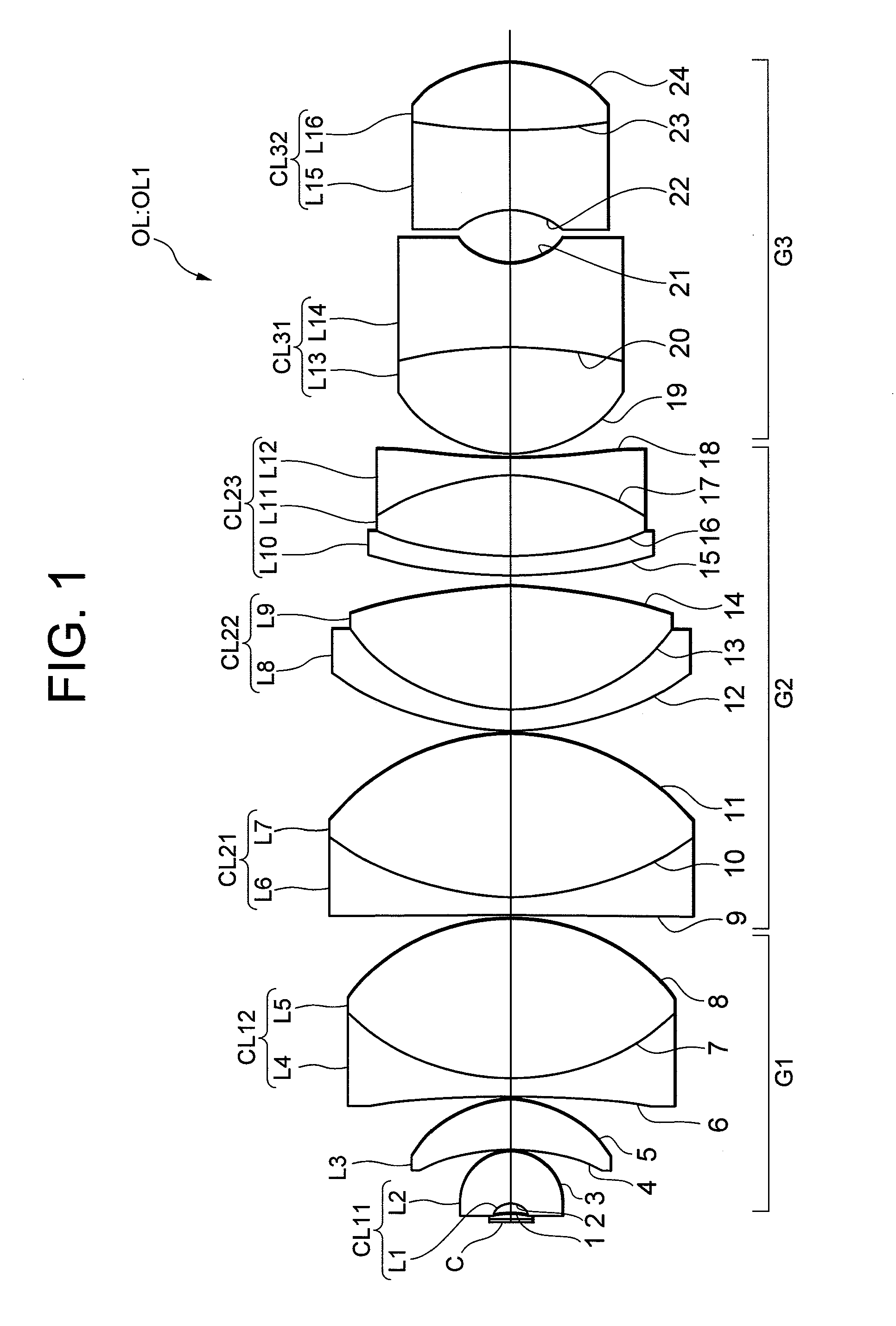
[0042]FIG. 1 used in the above explanation shows a microscope objective lens OL1 according to Example 1 of the present invention. As described above, the microscope objective lens OL1 is composed of, in order from a cover plate C side, a first lens group G1 having positive refractive power, a second lens group G2 having positive refractive power, and a third lens group G3 having negative refractive power. The first lens group G1 is composed of a cemented lens CL11 constructed by a positive meniscus lens (the first meniscus lens) L1 having a concave surface facing an object side cemented with a negative meniscus lens (the second meniscus lens) L2 having a concave surface facing the object side, a positive meniscus lens L3 having a concave surface facing the object side, and a cemented lens CL12 constructed by a double concave lens L4 cemented with a double convex lens L5. The second lens group G2 is composed of an achromatic lens CL21 constructed by a double concave lens L6 cemented ...
example 2
[0046]Then, a microscope objective lens OL2 shown in FIG. 3 is explained as Example 2. The microscope objective lens OL2 shown in FIG. 3 is composed of, in order from the cover glass C side, a first lens group G1 having positive refractive power, a second lens group G2 having positive refractive power and a third lens group G3 having negative refractive power. The first lens group G1 is composed of a cemented lens CL11 constructed by a positive meniscus lens L1 (the first meniscus lens) having a concave surface facing the object side cemented with a negative meniscus lens L2 (the second meniscus lens) having a concave surface facing the object side, a positive meniscus lens L3 having a concave surface facing the object side, and a cemented lens CL12 constructed by a double concave lens L4 cemented with a double convex lens L5. The second lens group G2 is composed of an achromatic lens CL21 constructed by a negative meniscus lens L6 having a convex surface facing the object side ceme...
example 3
[0049]Then, a microscope objective lens OL3 shown in FIG. 5 is explained as Example 3. The microscope objective lens OL3 shown in FIG. 5 is composed of, in order from the cover glass C side, a first lens group G1 having positive refractive power, a second lens group G2 having positive refractive power and a third lens group G3 having negative refractive power. The first lens group G1 is composed of a cemented lens CL11 constructed by a positive meniscus lens (the first meniscus lens) L1 having a concave surface facing the object side cemented with a negative meniscus lens (the second meniscus lens) L2 having a concave surface facing the object side, a positive meniscus lens L3 having a concave surface facing the object side, and a cemented lens CL12 constructed by a double concave lens L4 cemented with a double convex lens L5. The second lens group G2 is composed of an achromatic lens CL21 constructed by a negative meniscus lens L6 having a convex surface facing the object side ceme...
PUM
 Abstract
Description
Claims
Application Information