Transfer System

a technology of transfer system and transfer device, which is applied in the direction of metal-working feeding device, forging/hammering/pressing machine, manufacturing tools, etc., can solve the problem of cost factor, and achieve the effect of compact transfer system

Inactive Publication Date: 2010-08-12
SIEMENS AG
View PDF21 Cites 2 Cited by
  • Summary
  • Abstract
  • Description
  • Claims
  • Application Information

AI Technical Summary

Benefits of technology

[0008]An object of the invention is thus to design a more compact transfer system.

Problems solved by technology

The need to provide an electric motor in each case for each type of motion (arrows 20, 22 or 24), where the number of electric motors must even be doubled so that an electric motor effects the movement on both sides according to the type of motion, is a costly factor.

Method used


Image

  • Transfer System
  • Transfer System
  • Transfer System

Examples


Embodiment Construction

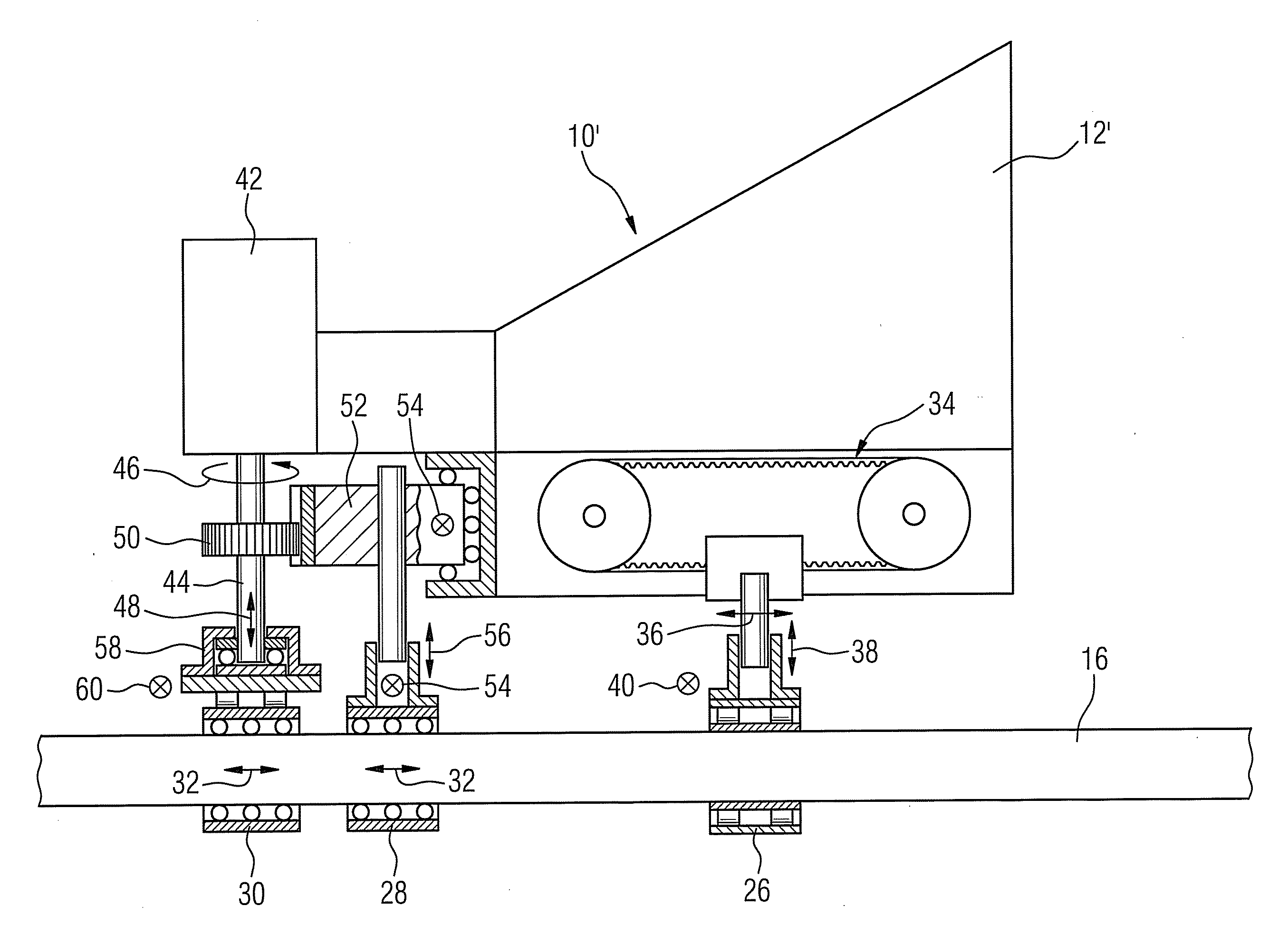
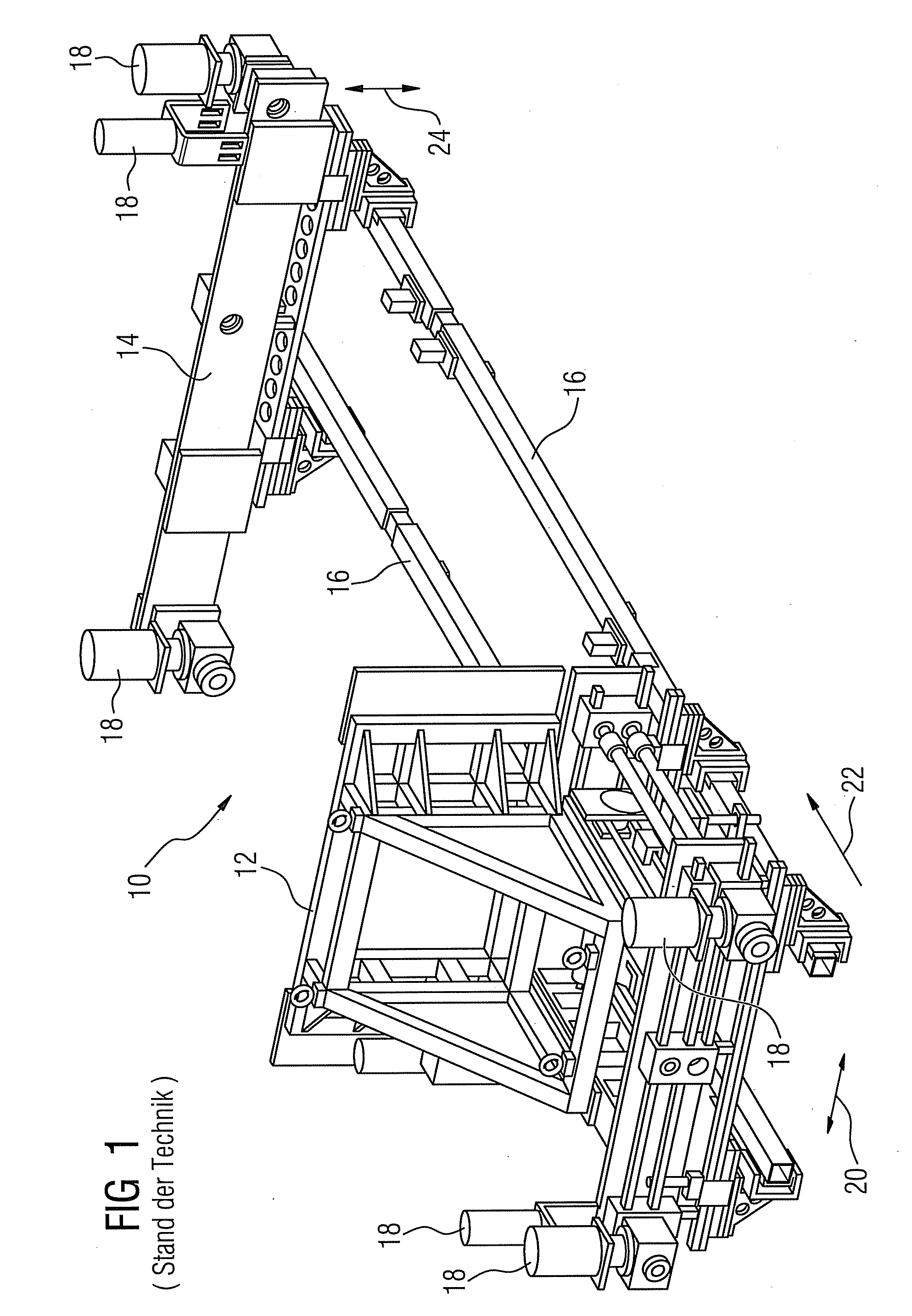
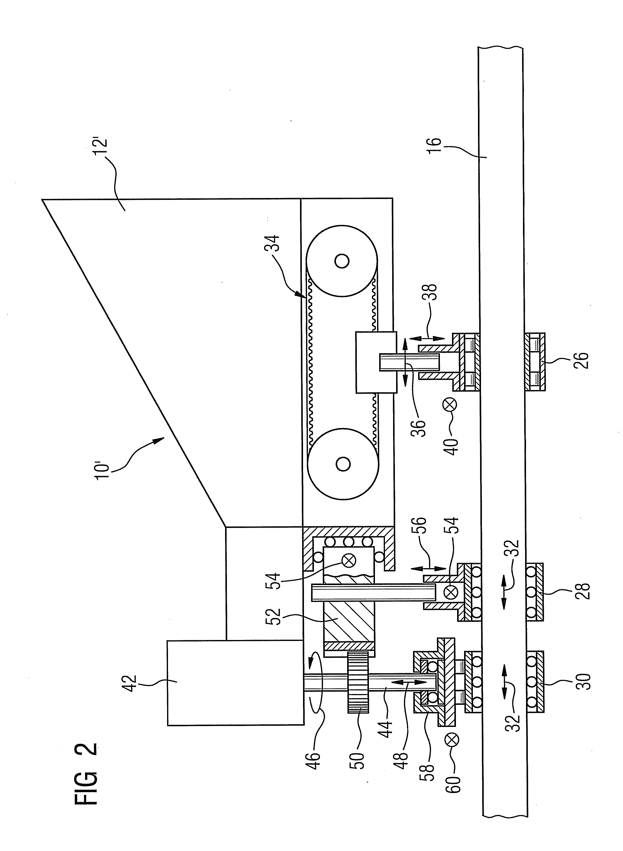
[0022]A transfer system 10′, of which, compared with FIG. 1, FIG. 2 shows just one side with the assembly structure 12′, comprises transport beams 16, which are to be moved in three directions in a mutually orthogonal manner. For each type of motion, a driver engages the transport beam 16, specifically one driver 26 for the advancement movement, one driver 28 for the transverse movement, in which the two transport beams 16 are moved towards, or as the case may be, away from each other, and one driver 30 for an upward or downward movement, for raising or lowering a workpiece. The driver 26 engages fixedly onto the transport beam 16, while the transport beam can be moved backwards and forwards16 relative to the drivers 28 and 30, see arrows 32. These different functionalities of the drivers 28 and 30 compared with the driver 26 as regards advancement movement of the transport beam 16 are reflected in a different mounting of the transport beam 6 in the drivers. The movement of the driv...


PUM

PropertyMeasurementUnit
lengthaaaaaaaaaa
movementaaaaaaaaaa
lengthaaaaaaaaaa

Abstract

In a transfer system, transport beams are displaced in three types of motions, i.e. toward each other, along a longitudinal extension thereof for advancement, and up and down. Two of these types of motions are triggered by a double-function motor. Such a double-function motor includes a shaft, which simultaneously rotates and displaces back and forth in linear fashion along the longitudinal extension thereof.

Description

CROSS REFERENCE TO RELATED APPLICATIONS[0001]This application is the US National Stage of International Application No. PCT / EP2008 / 052198 filed Feb. 22, 2008, and claims the benefit thereof. The International Application claims the benefits of German Patent Application No. 10 2007 009 747.8 DE filed Feb. 28, 2007; both of the applications are incorporated by reference herein in their entirety.FIELD OF INVENTION[0002]The invention relates to a transfer system. Such a transfer system, frequently also known for short as a transfer, is provided in conjunction with an arrangement of multiple presses. The transfer system has the task of transporting one workpiece from one tool to the next within a press.[0003]The transfer system here has two transport beams extending in a straight line, which can also be designated as gripper rails. The transport beams are parallel to each other. In a first type of motion they are too-free-moving to clamp a workpiece in position. In a second type of motio...

Claims


Application Information

Patent Timeline
Patent Type & Authority Applications(United States)
IPC IPC(8): B21D43/05B23Q7/00
CPCB21J13/08B21D43/055
Inventor EGERER, EMIL
Owner SIEMENS AG
Why Eureka
Try Eureka