Mold assembly

a mold and assembly technology, applied in the field of molds, can solve the problems of affecting the work efficiency of technicians, affecting the work efficiency of workers, and affecting the work efficiency of workers, and achieve the effect of greater thermal expansion and durable stainless steel shells

Active Publication Date: 2010-08-12
WENTWORTH MOLD
View PDF10 Cites 22 Cited by
  • Summary
  • Abstract
  • Description
  • Claims
  • Application Information

AI Technical Summary

Benefits of technology

[0012]The mold assembly may be adaptable for use with mold shells of different diameters or sizes without the need to change the carrier to accommodate different-sized shells, within predetermined operational parameters. In order to accommodate mold shells of a lesser diameter, thicker pads may be used in the mold assembly. In order to accommodate mold shells of a greater diameter, thinner pads may be used in the assembly. By changing the thickness of the pads used in the assembly, a mold carrier of constant diameter may accommodate mold shells having different diameters less than the diameter of the inner wall of the mold carriers.
[0013]Typically, the mold carrier and shell comprise similar materials to maintain acceptable tolerances between these parts during thermal expansion and contraction of the carrier and shell during mold operation. However, the use of pads of varying thickness permits for the use of dissimilar materials having different coefficients of thermal expansion. For example, stainless steel has a coefficient of thermal expansion less than the coefficient of thermal expansion of aluminum. Hence, the pads permit for a stainless steel shell to be used with an aluminum carrier because the stainless steel shell is directly heated to a temperature during operation which is greater than the temperature that the aluminum carrier reaches as a corollary of the close proximity of the carrier to the shell. Consequently, the thermal expansion of both the stainless steel shell and aluminum carrier in this application are within acceptable tolerances. This also allows for the use of a lighter aluminum carrier to that of a stainless steel carrier while having the advantage of a more durable stainless steel shell. It should be understood, however, that an aluminum shell may not be used with a stainless steel carrier in the same manner. Since the coefficient of thermal expansion of aluminum is greater than the coefficient of thermal expansion of stainless steel, the direct heating of the shell relative the carrier during mold operation would result in substantially greater thermal expansion in the aluminum shell than it would in the stainless steel carrier. Thereby, acceptable tolerances between the aluminum shell and the stainless steel carrier would not be maintainable.

Problems solved by technology

The problem with present molds is that heat dissipates away from the mold face to the outer walls of the mold requiring greater heat energy to maintain the elevated predetermined temperature.
Such heat dissipation may cause the outer walls of the mold to heat to a temperature which may be harmful to nearby components or to technicians who may come into contact with the heated mold outer wall.
In hot or cold fill mold assemblies where the mold shells are supported in direct contact with mold carriers, regular operation of the mold assembly may cause mechanical wear where there is contact between inner surfaces of the mold carriers and outer surfaces of the mold shells.
This wear may cause unnecessary mold damage and may hasten the need for expensive replacement of the carrier.
Moreover, since the mold shells are supported in direct contact by the carriers, the mold carrier is not adaptable to support a mold shell of a different diameter or size without changing the size of the carrier to suit the diameter of the new shell.
Another concern associated with contact between the mold half carriers and the mold half shells in mold assemblies is wear between the parts.

Method used


Image

  • Mold assembly
  • Mold assembly
  • Mold assembly

Examples


Embodiment Construction

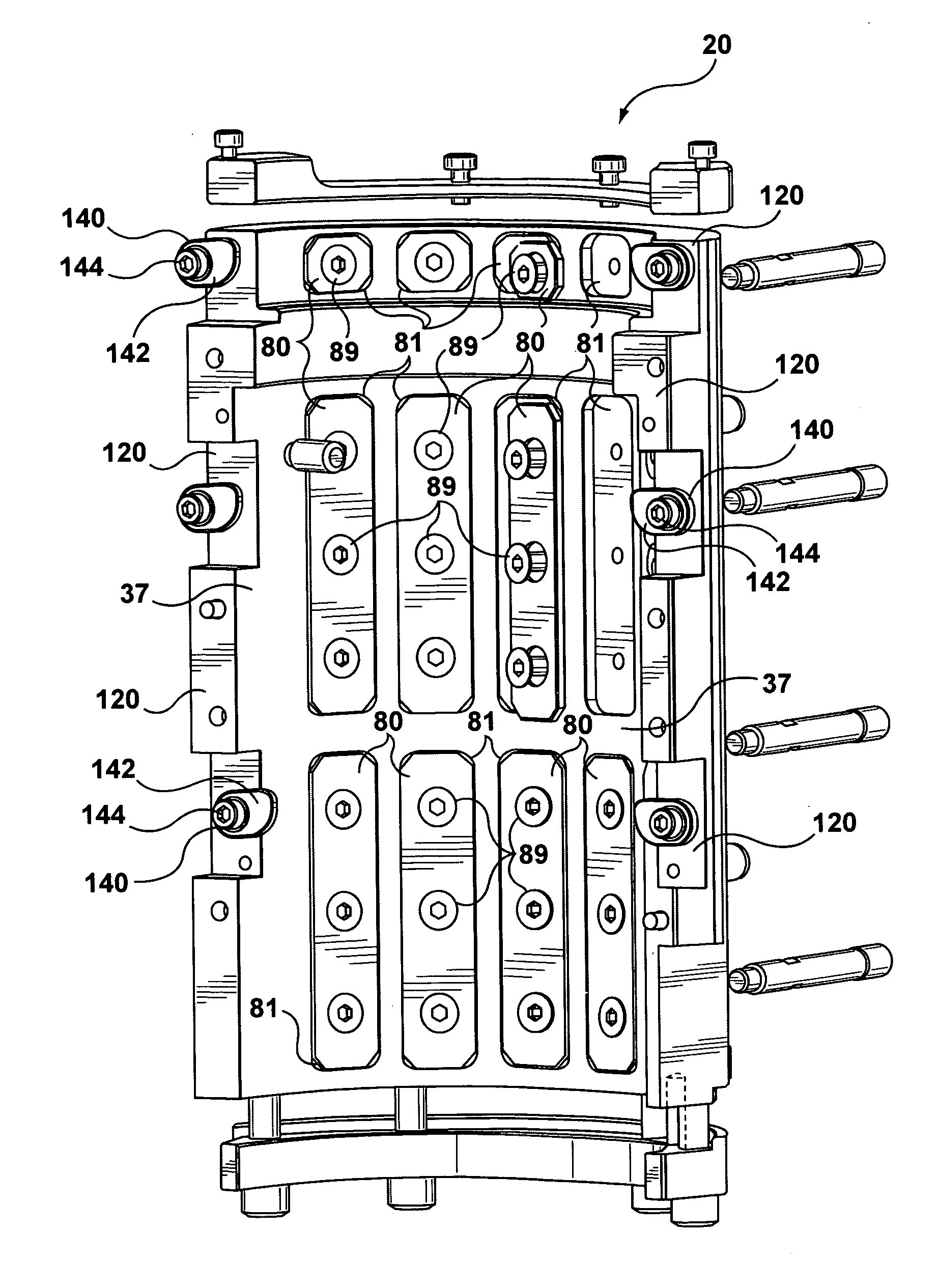
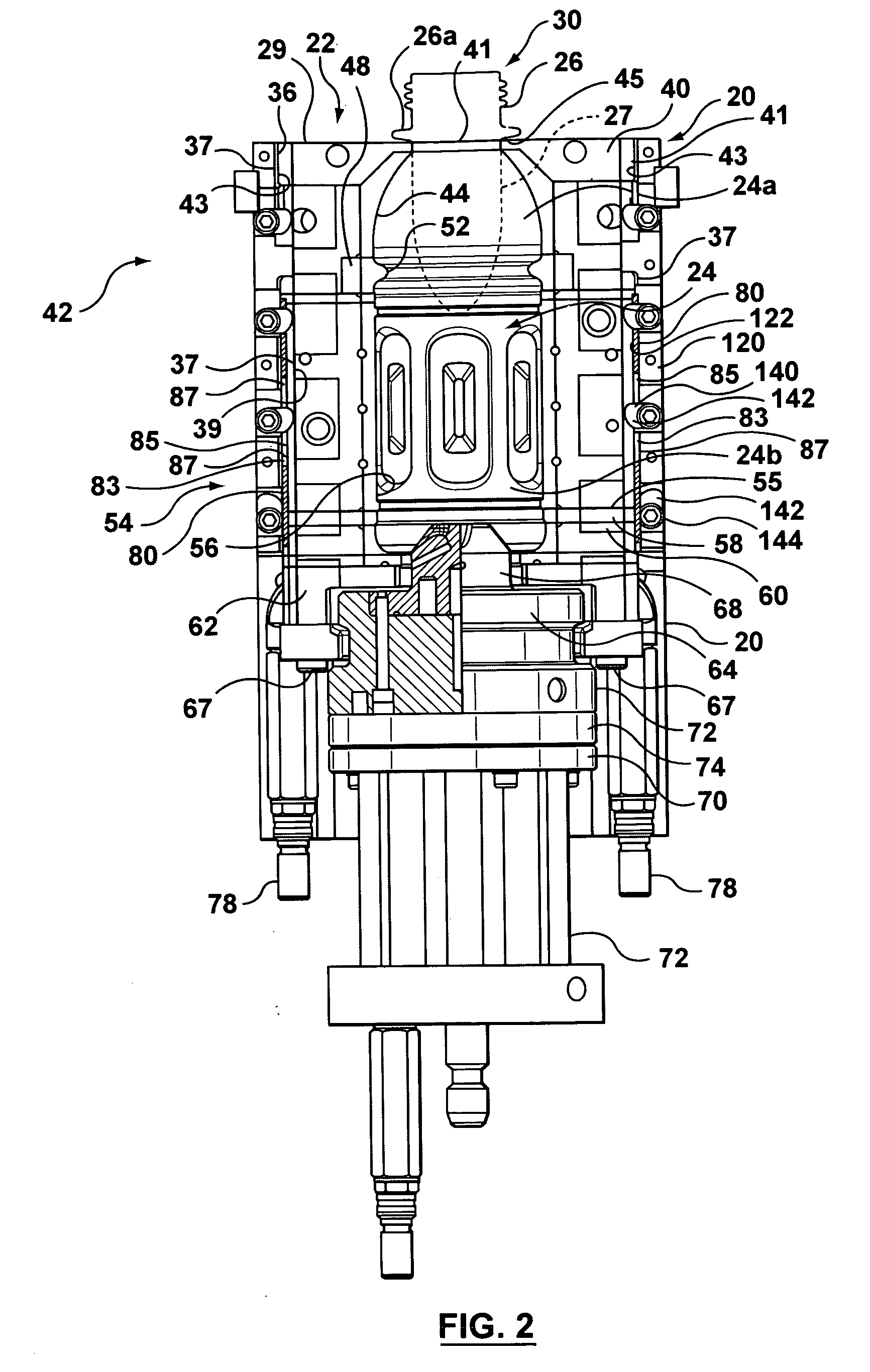
[0022]Referring to the drawings, the embodiments of the present invention are described. While the mold assembly described herein is adapted for making a hot fill PET bottle, it should be understood that the mold apparatus shown can be used for cold fill operations as well as for the manufacture of other types of containers where the mold face is changed, such as for example, soft drinks, cleansers and detergent-type containers, to name a few. In the exemplary embodiment, the mold half shell is made from stainless steel and the mold half carrier is made from aluminum. However, it should be understood that the mold half shells and the mold half carriers may be made from similar materials suitable for use in a mold assembly, such as for example, a stainless steel shell and carrier, or an aluminum shell and carrier.

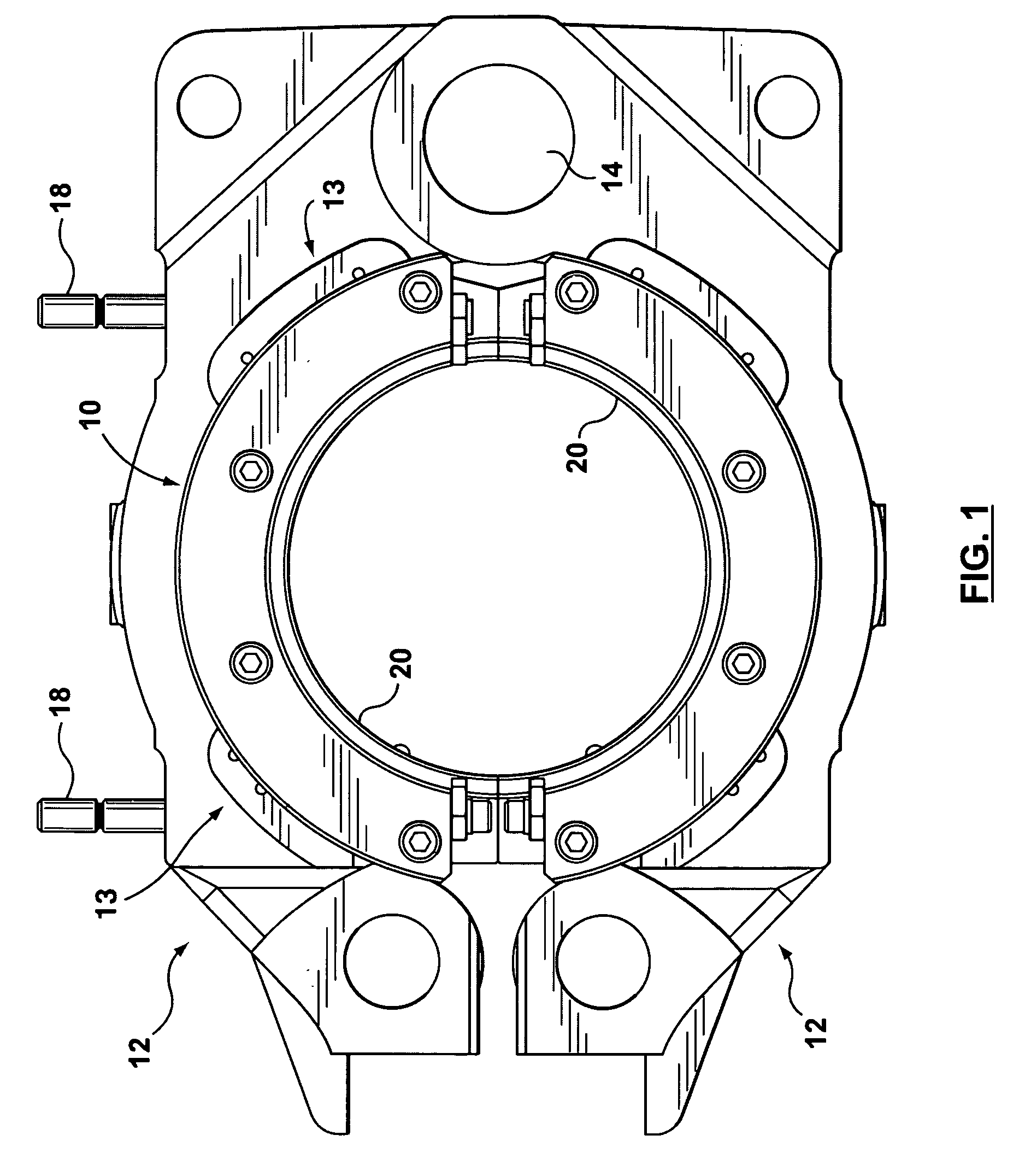
[0023]Referring to FIGS. 1 and 2, the mold assembly 10 is supported by a pair of support arms 12 which pivot about a pivot pin or axis 14. A lever arm (not shown in figures)...


PUM

PropertyMeasurementUnit
distanceaaaaaaaaaa
shapeaaaaaaaaaa
mechanicalaaaaaaaaaa

Abstract

A mold assembly has two mold half shells each having an outer and inner wall for defining the shape of a container to be formed. Two mold half carriers each have an inner wall overlaying and spaced from a corresponding mold shell outer wall for supporting the shells in the assembly. At least one insulating pad is sandwiched between the inner wall and the corresponding outer wall and is secured to one of the inner wall and the outer wall. The pad supports the outer wall in non-contacting and buffering relation relative the carrier inner wall. Each pad may be secured in a recessed seat in the respective wall. Pads may be secured in recessed seats having a depth less than the thickness of the pad. Pads absorb mold operational forces to reduce wear, reduce conduction from shell to carrier and facilitate the use of different-sized shells with one carrier.

Description

FIELD OF THE INVENTION[0001]The present invention relates to molds for making containers, and more particularly to molds having shell inserts carried by mold carriers where insulative pads are located between the outer walls of the shell and the inner walls of the carriers.DESCRIPTION OF THE RELATED ART[0002]Mold assemblies having two side mold parts and a base mold part are commonly used in the formation of plastic containers such as, for example, biaxially-oriented PET (polyethylene terephthalate) beverage bottles. The side mold parts may comprise a unitary half-part, multiple half-parts or a unitary shell half insert.[0003]In hot fill applications such as, for example, formation of juice containers that are subsequently filled with hot juices, it is important to maintain elevated temperature levels at the forming surface where the mold face contacts the plastic of the container to form a plastic container capable of withstanding hot filling temperatures of liquids subsequently fi...

Claims


Application Information

Patent Timeline
Patent Type & Authority Applications(United States)
IPC IPC(8): B29C33/02
CPCB29C33/02B29C2049/4864B29C2033/023B29C49/4823
Inventor TSAU, TARKYI, KYI SAN
Owner WENTWORTH MOLD
Why Eureka
Try Eureka