Torque measuring mechanism using cam engagement

a technology of cam engagement and torque measurement, which is applied in the direction of force/torque/work measurement apparatus, instruments, prosthesis, etc., can solve the problems of reducing the accuracy of the device, reducing the strength of the spring, and reducing the precision of the spring, so as to limit the torque within the device

Active Publication Date: 2010-08-12
BRADSHAW MEDICAL
View PDF28 Cites 17 Cited by
  • Summary
  • Abstract
  • Description
  • Claims
  • Application Information

AI Technical Summary

Benefits of technology

[0005]The cam interacts with a rolling member that is positioned between the cam and a plunger, with the interaction of these components providing the ability to limit the torque within the device. The rotation of the cam determines the amount of torque being delivered by the driver. The interaction allows the device to potentially have more than one preset level of torque being delivered by the tool.

Problems solved by technology

The large amount of force delivered by these devices tends to put a large amount of stress on the springs, which diminishes the strength of the spring, thereby reducing the precision of the spring.
Previous designs that use springs or beams, as discussed above, tend to wear after some use, thereby reducing the accuracy of the device.

Method used


Image

  • Torque measuring mechanism using cam engagement
  • Torque measuring mechanism using cam engagement
  • Torque measuring mechanism using cam engagement

Examples


Embodiment Construction

[0014]Although the disclosure hereof is detailed and exact to enable those skilled in the art to practice the invention, the physical embodiments herein disclosed merely exemplify the invention which may be embodied in other specific structures. While the preferred embodiment has been described, the details may be changed without departing from the invention, which is defined by the claims.

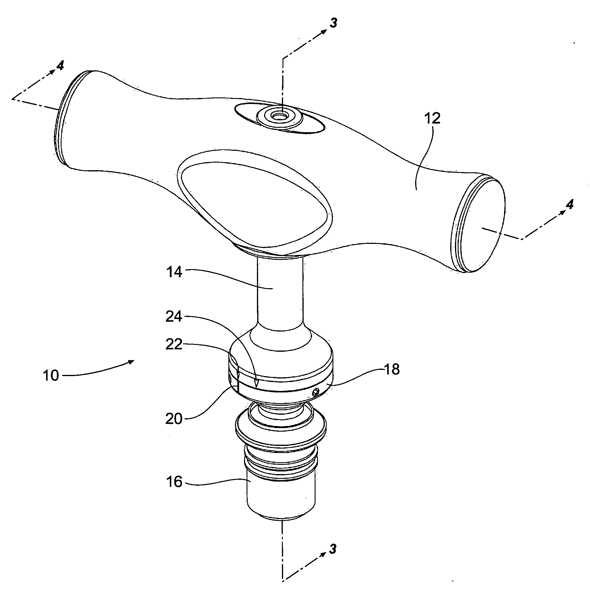
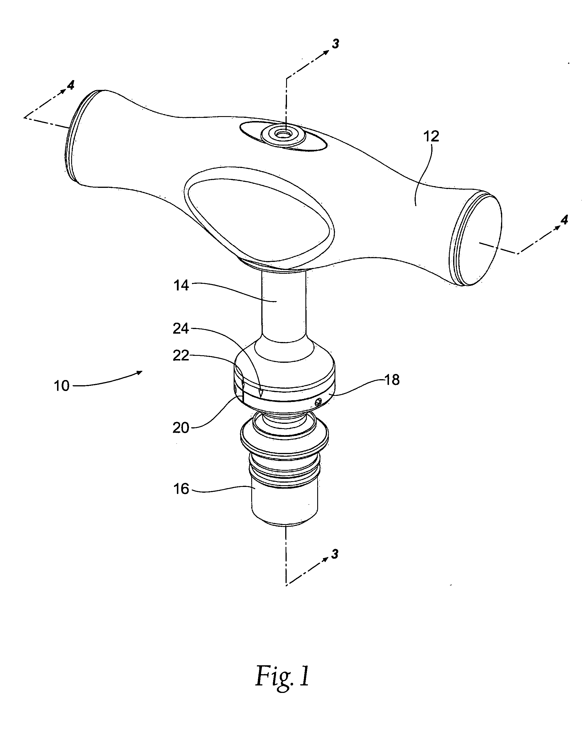
[0015]FIG. 1 provides a perspective view of a torque measuring driver 10 in accordance with the present invention. The driver 10 generally comprises a handle 12, a support sleeve or support section 14, and an adapter 16 that will allow attachment to a tool, such as a screwdriver, drill bit, wrench, or another similar device or tool (not shown). The driver 10 further comprises an adjustment ring 18 having an indicator 20 that will correspond to various torque measurements, such as markings 22 and 24 located on the external surface of the support section 14. The adjustment ring 18 allows the driver ...


PUM


Abstract

A device for delivering a predetermined amount of torque to a tool. The device has a handle and a cam assembly located within the handle. The cam assembly has a cam member integrally formed with a drive shaft. An adjustment ring is capable of rotating the cam assembly to different positions related to different levels of torque. A plunger will be biased against an exterior surface of the cam member to provide the different levels of torque delivery.

Description

BACKGROUND OF THE INVENTION [0001]The present invention relates to handheld tools and devices and, more particularly, to handheld tools and devices that have torque measuring mechanisms included with the tools.[0002]Screwdrivers, wrenches and the like have been developed to allow for varying degrees of torque to be delivered upon an object. These devices allow for different tensions or torques to be built into a torque-limiting device. Generally, such drivers use torsion springs or torsion beams in connection with a tensioning or biasing device to adjust or vary the amount of torque being delivered to an object. In certain devices and drivers, such as devices used in the medical field, these devices must be able to exert a large amount of force, while retaining a high level of precision. The large amount of force delivered by these devices tends to put a large amount of stress on the springs, which diminishes the strength of the spring, thereby reducing the precision of the spring.[...

Claims


Application Information

Patent Timeline
Patent Type & Authority Applications(United States)
IPC IPC(8): A61B17/58
CPCA61B17/8875B25B23/1427A61B2019/464A61B2019/301A61B2090/064A61B2090/031
Inventor GAO, HUA
Owner BRADSHAW MEDICAL
Why Eureka
Try Eureka