
Rear wheel steering control system

a steering control and rear wheel technology, applied in steering initiation, instruments, vessel construction, etc., can solve problems such as adversely affecting and achieve the effect of improving the ride quality of the vehicl

Inactive Publication Date: 2010-08-12
HONDA MOTOR CO LTD
View PDF13 Cites 22 Cited by
  • Summary
  • Abstract
  • Description
  • Claims
  • Application Information

AI Technical Summary

Benefits of technology

[0004]In view of such problems of the prior art, a primary object of the present invention is to provide a rear wheel steering control system that can improve the ride quality of a vehicle fitted with a rear wheel steering control system.
[0005]A second object of the present invention is to provide a rear wheel steering control system which is highly simple and compact in structure.
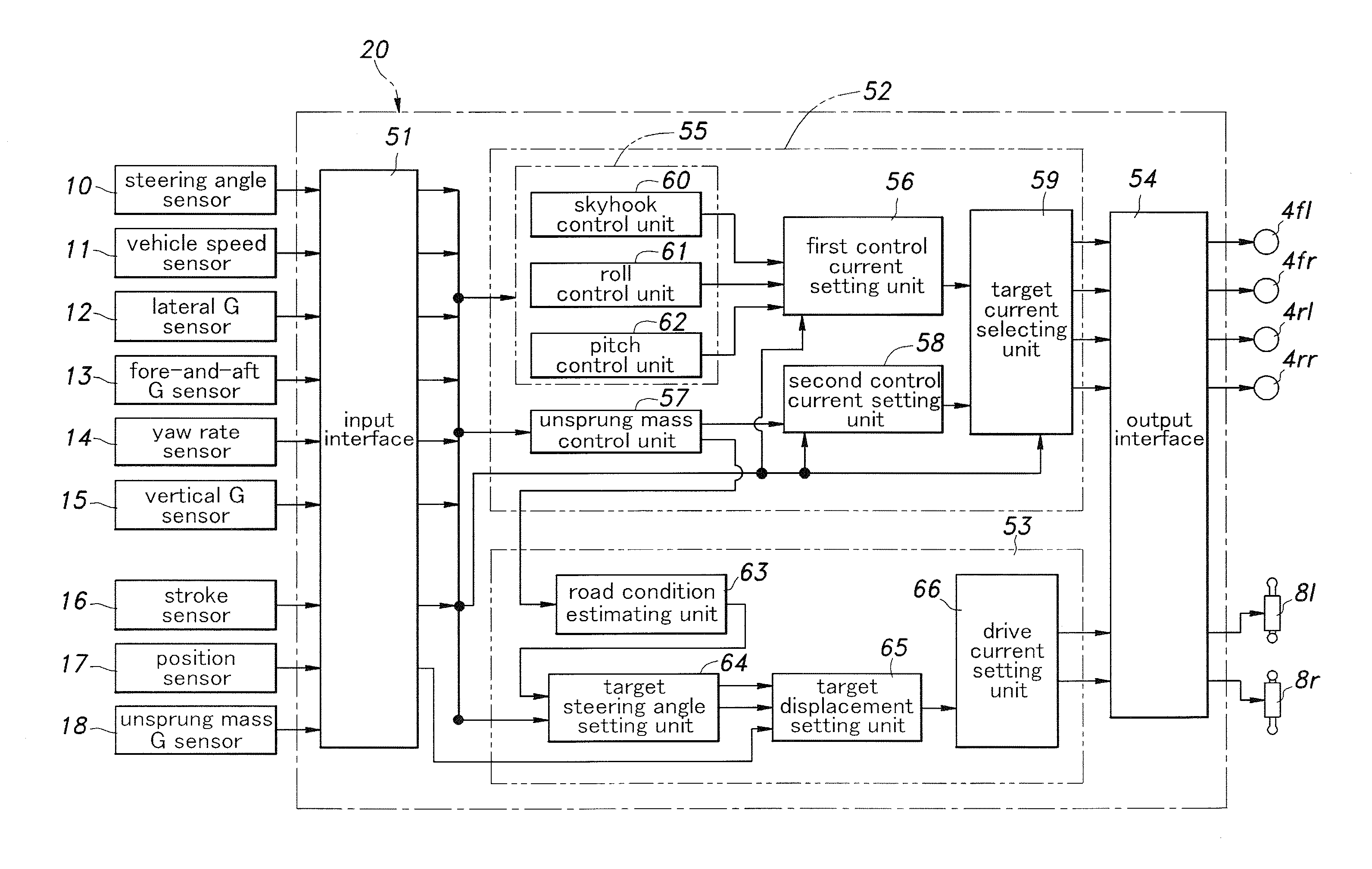
[0007]Thereby, when the vehicle is traveling over a rough road surface, the actuator is forced to the neutral position, and the rear wheels are brought to a neutral position so that the changes in the wheel geometry (tread and / or alignment) of the rear wheels at the time of a bump or a rebound can be avoided. Therefore, the ride quality of a vehicle equipped with the rear wheel steering control system is favorably maintained even when the vehicle is traveling over a road surface, and the rear wheels undergo large vertical displacements.
[0008]According to a preferred embodiment of the present invention, the vehicle is additionally fitted with an unsprung mass control unit, and the road condition estimating unit is enabled to determine the state of road condition from a manipulated variable of the unsprung mass control unit. Thereby, the state of the road surface can be accurately determined in a simple and inexpensive manner.

Problems solved by technology

Therefore, as the toe angle of the rear wheel is changed, the geometry of the wheel, in particular the tread of the rear wheels, changes at the times of bump and rebound, and this may adversely affect the ride quality of the vehicle.

Method used


Image

  • Rear wheel steering control system
  • Rear wheel steering control system
  • Rear wheel steering control system

Examples


Embodiment Construction

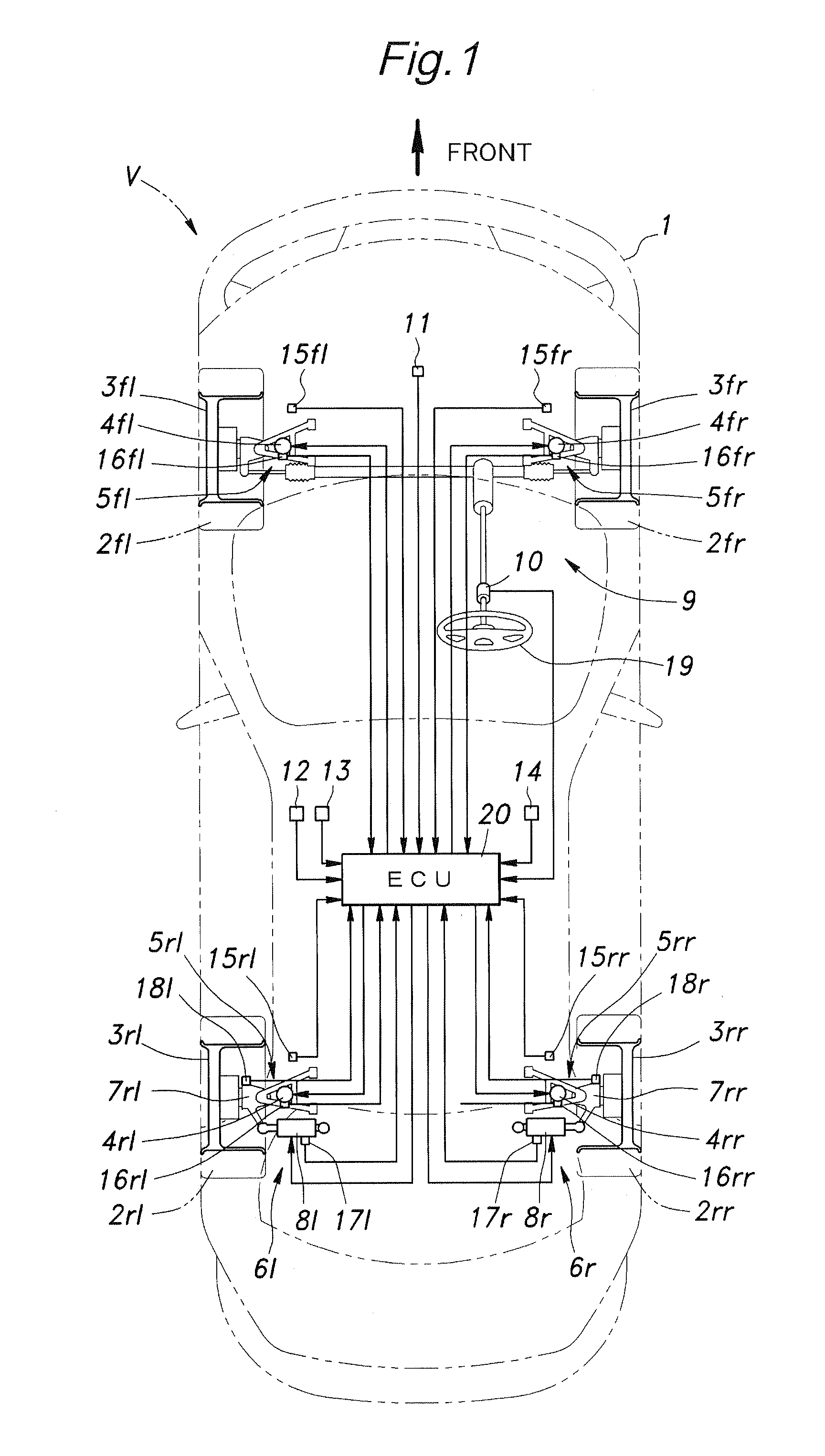
[0016]A preferred embodiment of the rear wheel steering control system of the present invention is described in the following with reference to FIG. 1. In FIG. 1, some of the components thereof are associated with each wheel, and such component parts are denoted with suffices fl, fr, rl and rr to indicate with which wheel the particular component is associated. For instance, a front left wheel is denoted with 3fl, a front right wheel with 3fr, a rear left wheel with 3rl and rear right wheel with 3rr. When a particular component is collectively referred to, it may be denoted with the corresponding numeral without the suffix. For instance, the wheels of the vehicle may be referred to simply as 3 depending on the situation.

[0017]Referring to FIG. 1, the illustrated vehicle V has a vehicle body 1 which has four wheels 3 each fitted with a pneumatic tire 2. Each wheel 3 is rotatably supported by a knuckle 7 which is in turn supported by wheel suspension system 5 including suspension arms...


PUM


Abstract

In a rear wheel steering control system for a vehicle, a rear wheel steering control unit (53) forces the toe angle of each rear wheel (3rl, 3rr) to a substantially neutral position or a slightly toe-in position when a road condition estimating unit (63) has detected a rough road surface. Thereby, when the vehicle is traveling over a rough road surface, the actuator is forced to the neutral position, and the rear wheels are brought to a neutral position so that the changes in the wheel geometry (tread and / or alignment) of the rear wheels at the time of a bump or a rebound can be avoided. Therefore, the ride quality of a vehicle equipped with the rear wheel steering control system is favorably maintained even when the vehicle is traveling over a road surface, and the rear wheels undergo large vertical displacements.

Description

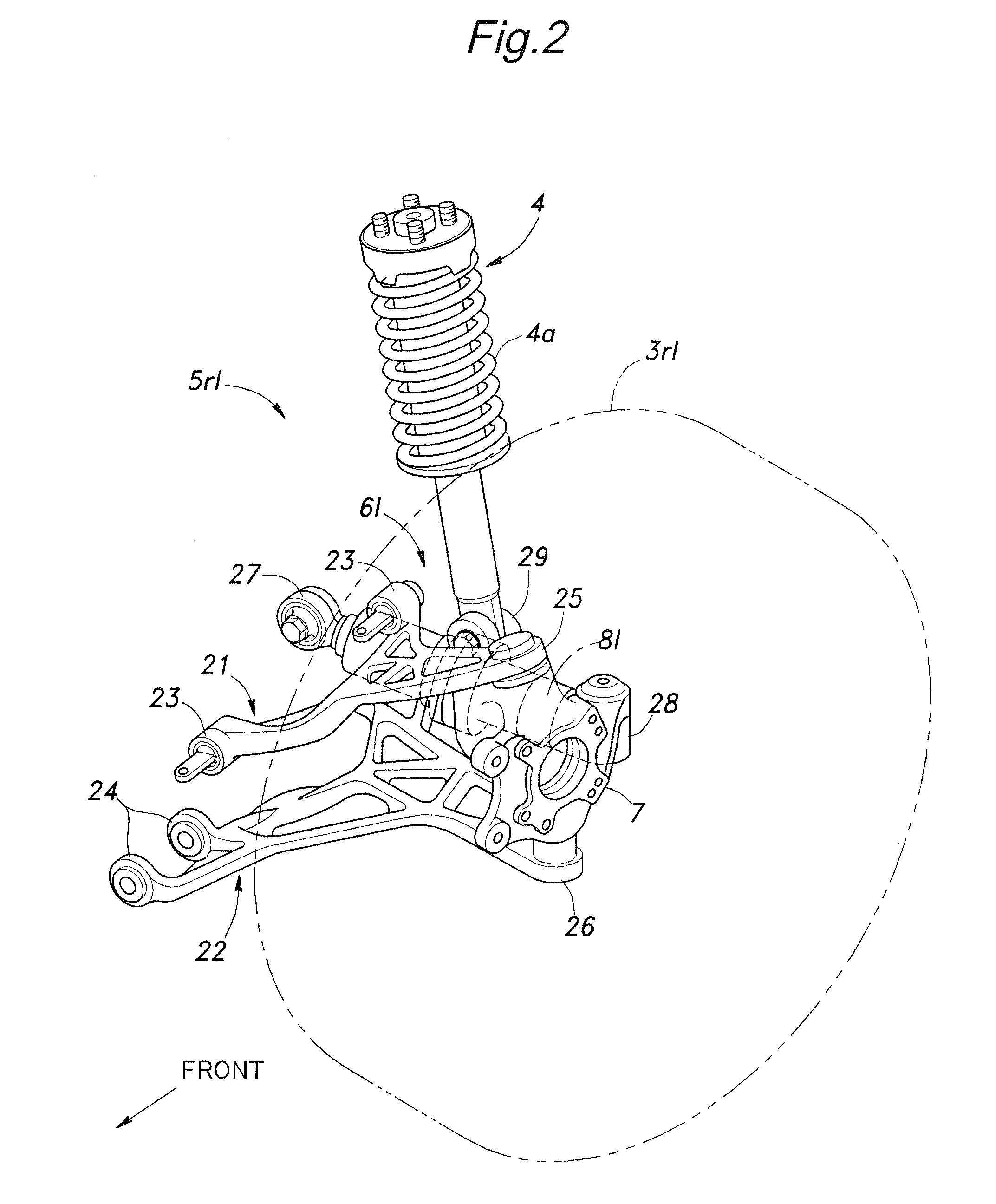
TECHNICAL FIELD[0001]The present invention relates to a rear wheel steering control system that can change the toe angles of rear wheels of a vehicle.BACKGROUND OF THE INVENTION[0002]It has been proposed to fit a four-wheeled vehicle with a rear wheel steering control system in addition to a more conventional front wheel steering system for the purpose of improving the driving stability of the vehicle. Typically, in association with each rear wheel is provided an electric linear actuator having an output rod that can be selectively extended and retracted so that the two rear wheels may be steered individually. See Japanese patent laid open publication No. 9-030438, for instance.[0003]The linear actuator may be advantageously incorporated into one of the lateral arms that form a part of the wheel suspension system of the corresponding rear wheel. In such a case, changing the toe angle of the rear wheel is effected by changing the length of such a lateral arm. Therefore, as the toe an...

Claims


Application Information

Patent Timeline
IPC IPC(8): G06F19/00B60G17/015B60G17/018B62D5/04B62D6/00B62D7/08B62D101/00B62D103/00B62D111/00B62D113/00B62D137/00
CPCB60G7/003B60G17/0165B60G2200/462B60G2202/42B60G2204/62B62D17/00B60G2400/821B60G2500/40B60G2800/162B60G2800/962B62D7/146B60G2206/1116
Inventor NISHIOKA, TAKASHI
Owner HONDA MOTOR CO LTD
Learn More