
Tube cutting device and method thereof

a cutting device and tube technology, applied in the direction of tube shearing machines, nuclear elements, greenhouse gas reduction, etc., can solve the problems of reducing affecting the maintenance of the whole reactor, and the current available cutting equipment can be very expensive, so as to achieve the effect of enhancing the safety of tube cutting operation

Inactive Publication Date: 2010-08-19
INST NUCLEAR ENERGY RES ROCAEC
View PDF27 Cites 4 Cited by
  • Summary
  • Abstract
  • Description
  • Claims
  • Application Information

AI Technical Summary

Benefits of technology

The present invention is a tube cutting device that can perform a remote tube cutting operation quickly and safely. It prevents direct contact with the tube and reduces the risk of injury to operators. The device is simple and low-cost, with high cutting efficiency. It includes a holding unit, a cutting unit, and a control unit connected in a remote manner. The control unit directs the holding unit to hold and move the tube to a specific position, and then the cutting unit performs the cutting operation by the operator's directions.

Problems solved by technology

It is noted that the sleeve can be deformed or damaged after being used for a period of time and thus requires to be replaced for facilitating the smooth passing of the neutron monitor.
Thus, those currently available cutting equipments capable of such operation can be very expensive.
In addition, as there can be as many as fifty sleeves in a nuclear reactor, the cutting operation can be time consuming that can slow down the whole reactor maintenance procedure.

Method used


Image

  • Tube cutting device and method thereof
  • Tube cutting device and method thereof
  • Tube cutting device and method thereof

Examples


Embodiment Construction

[0018]For your esteemed members of reviewing committee to further understand and recognize the fulfilled functions and structural characteristics of the invention, several preferable embodiments cooperating with detailed description are presented as the follows.

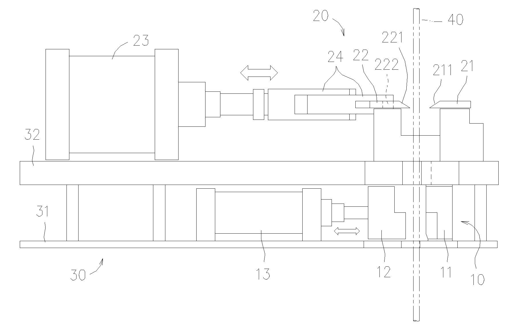
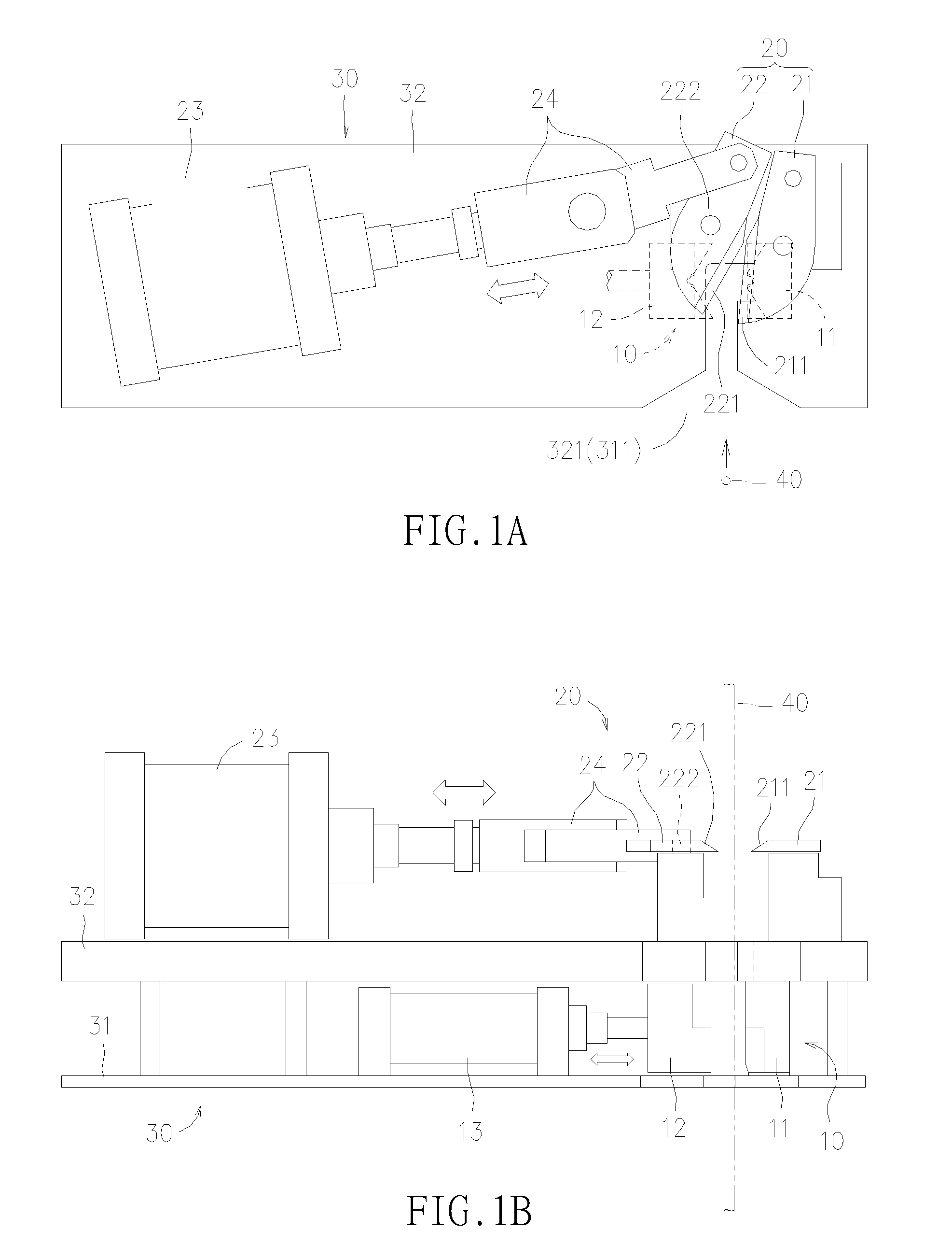
[0019]As seen in FIG. 1A and FIG. 1B, a tube cutting device is comprised of a holding unit 10, a cutting unit 20 and a control unit. Both the holding unit 10 and the cutting unit 20 are mounted on a frame 30, while the holding unit 10 arranged at a lower layer 31 of the frame 30 and the cutting unit 20 is arranged at an upper layer 32 of the frame 30. The frame 30 can be driven to perform a reciprocating motion while bringing along both the holding unit 10 and the cutting unit 20 to move synchronously.

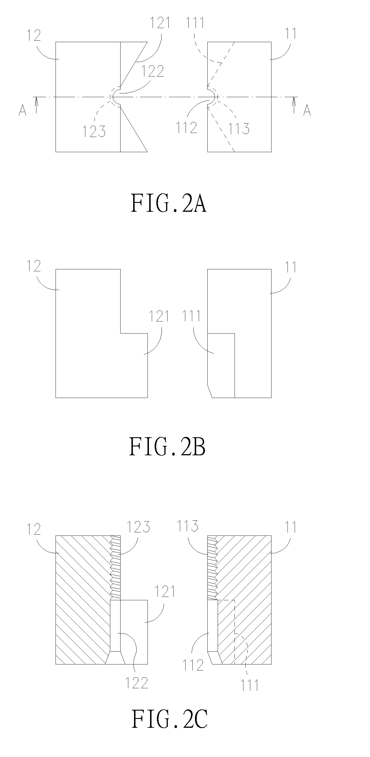
[0020]As seen in FIGS. 1A˜2C, the holding unit 10, adapted for clipping upon a tube 40, is comprised of a fixing part 11 and a mobile part 12. The fixing part 11 is fixedly mounted on the frame 30 while the mobile part 12, conne...


PUM

PropertyMeasurementUnit
length L1aaaaaaaaaa
lengthaaaaaaaaaa
lengthaaaaaaaaaa

Abstract

A tube cutting device and method thereof are disclosed, which are adapted for performing a remote tube cutting operation upon a tube. The tube cutting device is comprised of: a holding unit; a cutting unit; and a control unit, connected to the holding unit and the cutting unit in a remote manner; wherein, the control unit is capable of directing the holding unit to hold and move a tube to a specific position and thereafter directing the cutting unit to perform a cutting operation upon the tube. With the aforesaid tube cutting device, an operator operating the tube cutting device can perform an cutting operation upon the tube remotely without having to contact directly with the tube, and thus the operator is prevented from having to stay in a working environment containing hazardous materials, such as radioactive pollutants, gas / liquid with strong acid or alkali, etc., so that the safety of the tube cutting operation can be enhanced. In addition, as the tube cutting device is simple in structure, the manufacturing cost thereof is comparatively low but still possess high cutting efficiency.

Description

FIELD OF THE INVENTION[0001]The present invention relates to a tube cutting device, and more particularly, to an apparatus capable of performing a remote tube cutting operation upon a tube in a rapid manner, by which direct contacting with the tube or other tube-relating components can be prevented and thus an operator operating the tube cutting device is prevented from having to stay in a working environment containing hazardous materials, so that the safety of the tube cutting operation can be enhanced and therefore the tube cutting device is especially suitable for applications involving working in environment of radioactive pollutants, gas / liquid with strong acid / alkali, etc.BACKGROUND OF THE INVENTION[0002]The implementation of the safety policy on site for ensuring a safe working environment is becoming a common sense, since most industries had realized that a safe working environment not only can minimizing the chance that its workers is suffered by work-related health and sa...

Claims


Application Information

Patent Timeline
Patent Type & Authority Applications(United States)
IPC IPC(8): B23D21/00B26D5/20B26D7/06B23D36/00
CPCB23D21/00G21C17/017G21Y2002/302G21Y2004/504G21Y2002/501G21Y2004/501G21Y2002/401Y10T83/0596Y10T83/7493Y10T83/162Y10T83/8821Y10T83/7573Y02E30/30
Inventor YU, YU-HUANGCHANG, CHENG-HANSHYU, JONG-SHULIU, YUN-HUILIN, TAING-YITIENG, SHEN-YUEHCHIU, WAN-JUNE
Owner INST NUCLEAR ENERGY RES ROCAEC
Learn More