Device for the deposition of layers

a technology for devices and layers, applied in the direction of electrostatic spraying apparatus, domestic objects, applications, etc., can solve the problems of difficult to act on the environmental conditions of enclosures, and difficult to maintain sufficient sterility conditions, etc., to achieve sufficient sterility and reduce manufacturing costs.

Inactive Publication Date: 2010-08-19
BERNER FACHHOCHSCHULE FUR TECHN & INFORMATIK
View PDF8 Cites 50 Cited by
  • Summary
  • Abstract
  • Description
  • Claims
  • Application Information

AI Technical Summary

Benefits of technology

[0011]This aim is achieved thanks to the fact that, according to the invention, the frame is furthermore provided with an enclosure inside which at least the plate and the end of the nozzle are arranged, and outside this enclosure at least the means for controlling the movement of the table and of the dispenser and the control member are arranged. In this way, the implant can be manufactured directly in the operating room in which the implant must be put into place, or in a production environment meeting the standards necessary for the manufacture of medical implants such as GMP (Good Manufacturing Practice), thereby reducing the risks of infection and contamination of patients.
[0015]Optimal conditions for manufacturing the object can be obtained with an extrusion member of the piezoelectric type. This makes it possible to dispense the material at a high speed and a very precise dosing. This technology allows the synchronization of the movement of the table and the dosing of the deposited material, which guarantees optimal homogeneity of the deposited pattern.

Problems solved by technology

Taking all of these precautions is very costly.
Such a device makes it possible to reduce the risks of infection of the manufactured implant, but through the principle of successive layer deposition, the initially sterile enclosure will have to be pierced with a large number of holes, making it particularly difficult to maintain sufficient sterility conditions.
Moreover, when the enclosure is pierced with many holes, it becomes particularly difficult or even impossible to act on the environmental conditions of the enclosures.
It will be impossible, for instance, to maintain a significant overpressure in the enclosure, during or after the manufacture of the object.

Method used


Image

  • Device for the deposition of layers
  • Device for the deposition of layers
  • Device for the deposition of layers

Examples


Embodiment Construction

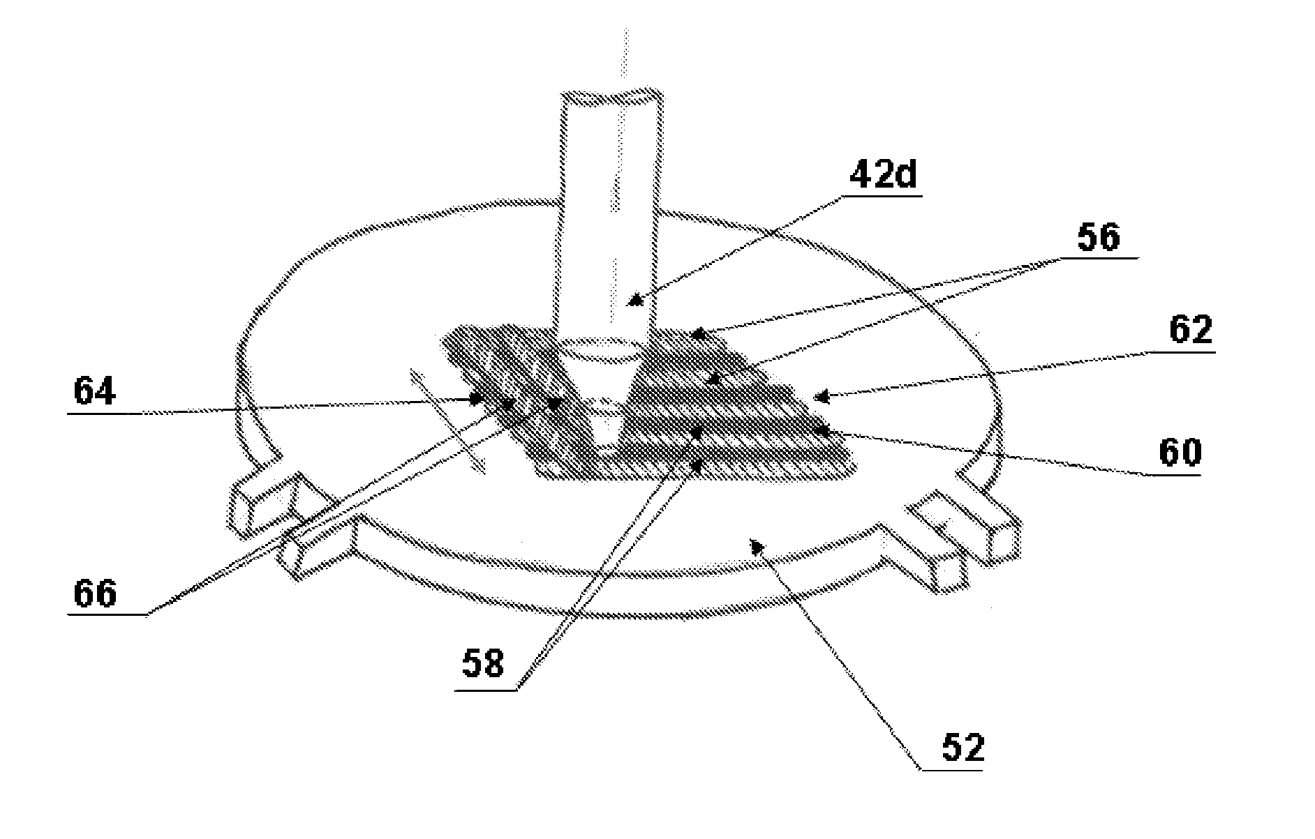
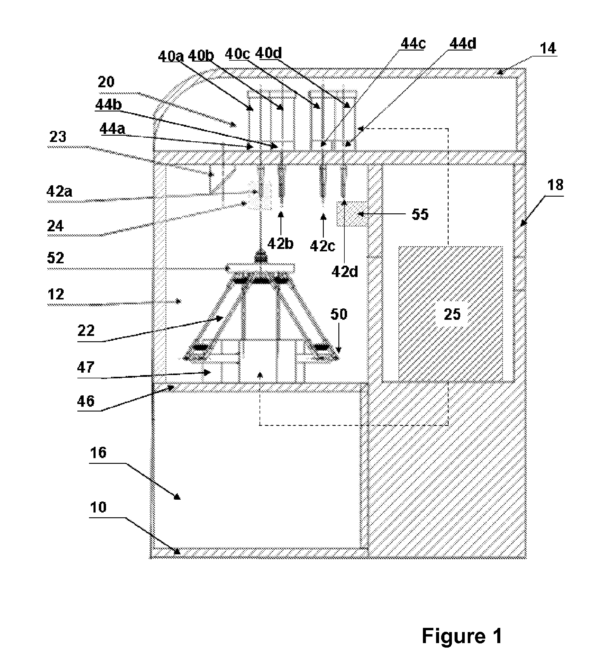
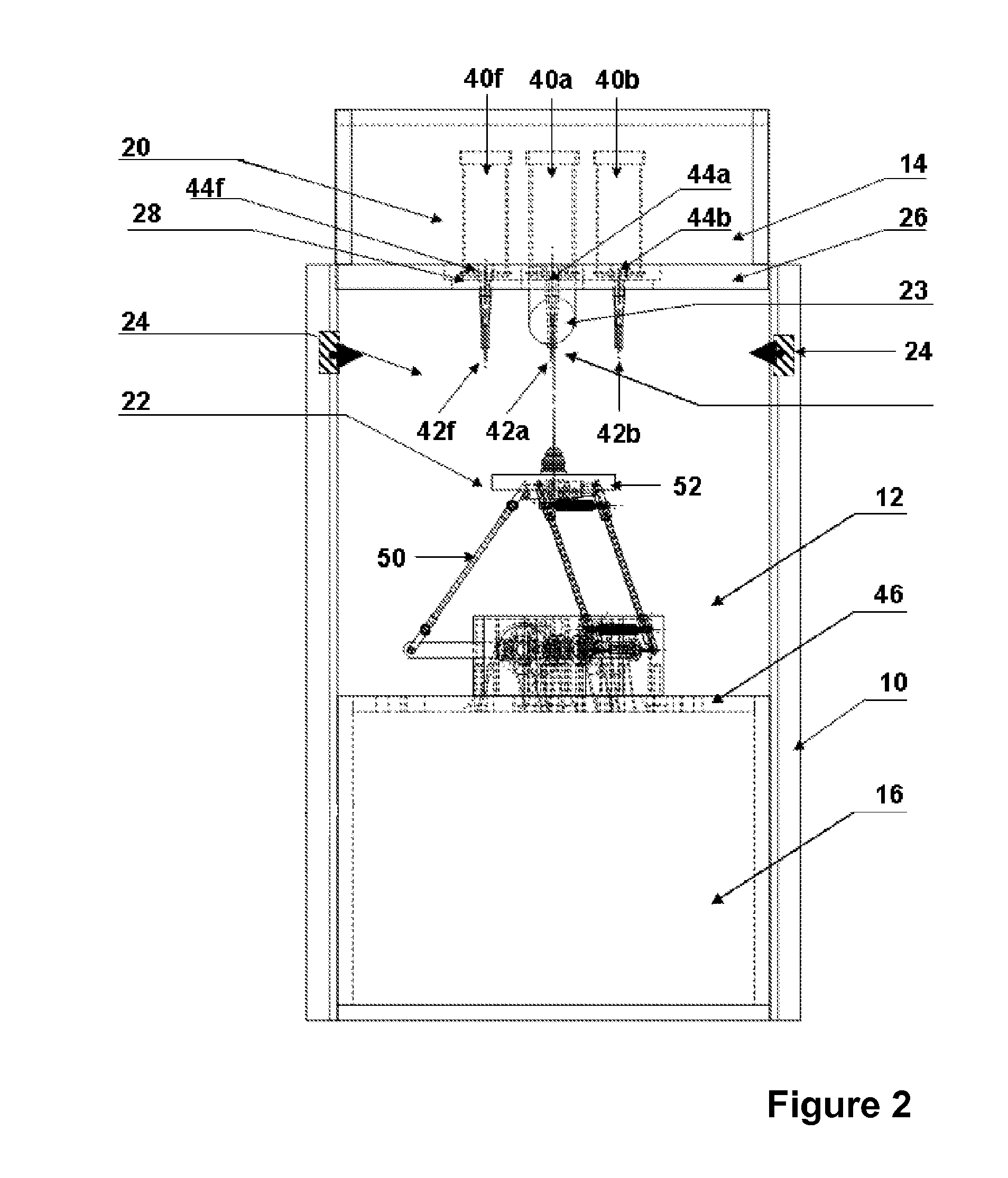
[0026]The device illustrated in FIGS. 1 and 2 comprises a frame 10 provided with partitions and doors which define four housings 12, 14, 16 and 18, inside which are arranged a dispenser 20, a movable table 22 and compacting means 23, which will be described more precisely below, as well as a position sensor 24 and a control member 25.

[0027]The walls forming the central housing 12 are fixed on the frame 10, in a manner well known by one skilled in the art, in order to form an enclosure sufficiently sealed to ensure its cleanliness, and thereby avoid physical elements (e.g. dust or textile fibers), biological elements (e.g. bacteria, viruses or any other type of micro-organism) or chemical elements (molecules in gaseous, solid or liquid form) from penetrating inside the housing 12, condition which is crucial to ensure a sterile environment as required for the manufacture of medical implants.

[0028]As can be seen more precisely in FIGS. 3 and 4, the upper wall of the housing 12, which a...


PUM

PropertyMeasurementUnit
diameteraaaaaaaaaa
wavelengthaaaaaaaaaa

Abstract

A device for the deposition of layers, includes a frame (10) provided with a housing (12), the frame further including: a table (22) for bearing an object to be manufactured and provided with a mobile plate (52) and first movement element (48), a material dispenser (20) for placing the material on the table (52) for manufacturing the object, provided with second movement element (34, 36, 38) for at least one vessel (40), at least one nozzle (42) and at least one extrusion member (44); a compacting element (23), and a control member (25) for controlling the material deposition on the table (22). At least the plate (52) and the end of the nozzle (42) are provided inside the housing (12), while at least the table movement element (48) and the dispenser movement element (34, 36, 38) and the control member (25) are provided outside the housing (12).

Description

FIELD OF THE INVENTION [0001]The present invention relates to a device for the manufacture of an object through deposition of layers, in particular successive layers of a material forming a stratified structure in the object.DESCRIPTION OF THE PRIOR ART [0002]Such devices are well-known, and are for example described in documents U.S. Pat. No. 5,136,515 and US 2003 / 209836. They include:[0003]a frame bearing:[0004]a table designed to support an object to be manufactured and provided with a movable plate, first means for controlling a movement and first guide means,[0005]a material dispenser, designed to arrange this material on the table in order to form said object, provided with second means for controlling a movement and second guide means, at least one container in which the material is found, at least one nozzle connected to the container and allowing the passage of the material toward said table, and at least one extrusion member,[0006]compacting means for making the material t...

Claims


Application Information

Patent Timeline
Patent Type & Authority Applications(United States)
IPC IPC(8): B05C9/12B05C5/00
CPCB29C67/0055B29L2031/7546B29L2031/7532B29C64/106
Inventor THURNER, MARCMUSSARD, YVES
Owner BERNER FACHHOCHSCHULE FUR TECHN & INFORMATIK
Why Eureka
Try Eureka