LED lighting device

Inactive Publication Date: 2010-08-19
PANASONIC CORP
View PDF20 Cites 39 Cited by
  • Summary
  • Abstract
  • Description
  • Claims
  • Application Information

AI Technical Summary

Benefits of technology

[0015]It is also preferred that each the light emitting unit further includes a frame. The frame surrounds the phosphor over an entire side surface of the phosphor. The frame is shaped to reflect the light from the phosphor. In this case, it is also possible for each one of the light emitting units to produce a predetermined color of light with no effect of the light emitted from the other light emi

Problems solved by technology

Further, the LED chips respectively have aged deterioration properties which are also different from each other.
That is, the LED lighting device faces a problem of a

Method used


Image

  • LED lighting device
  • LED lighting device
  • LED lighting device

Examples


first embodiment

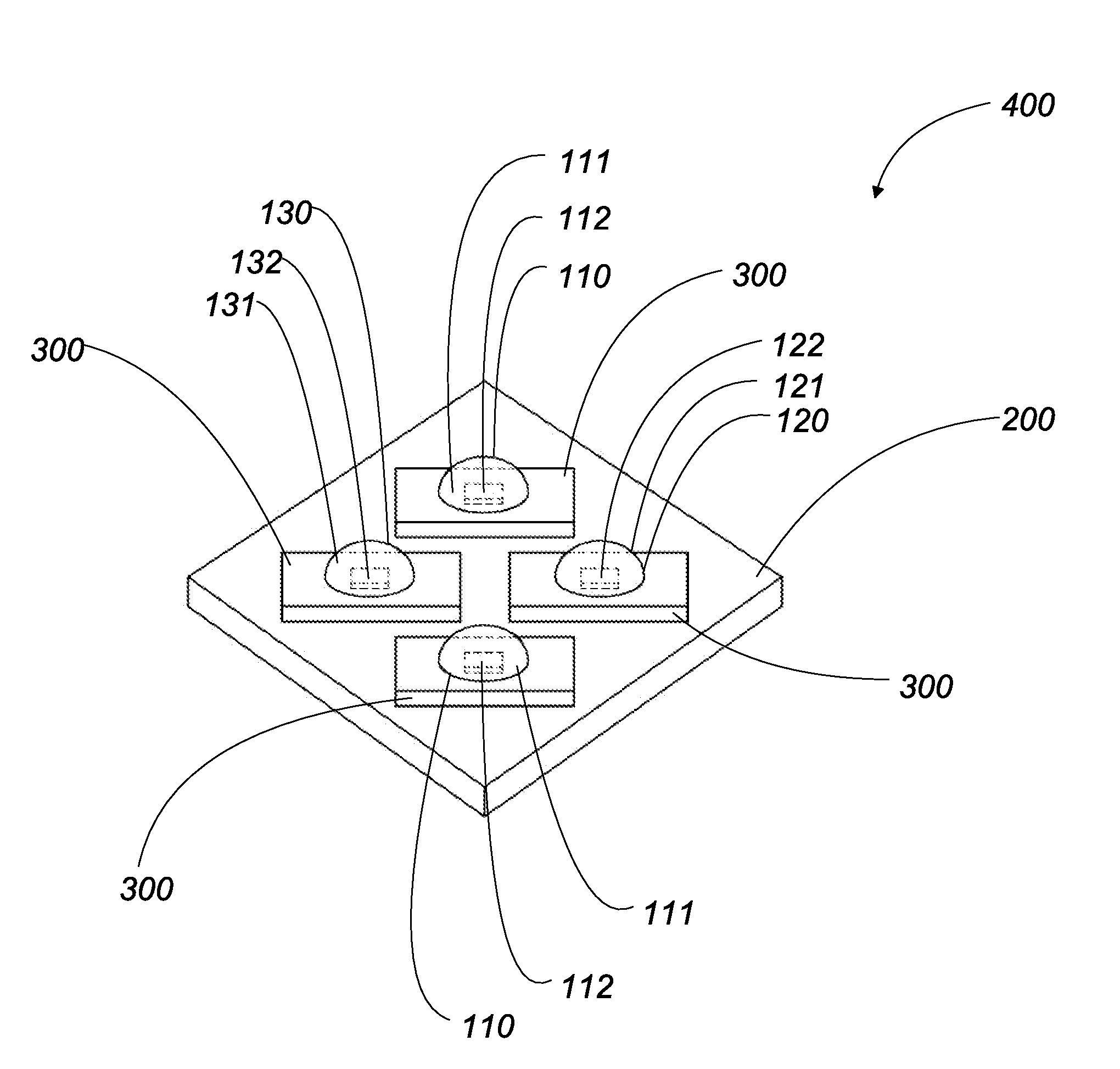
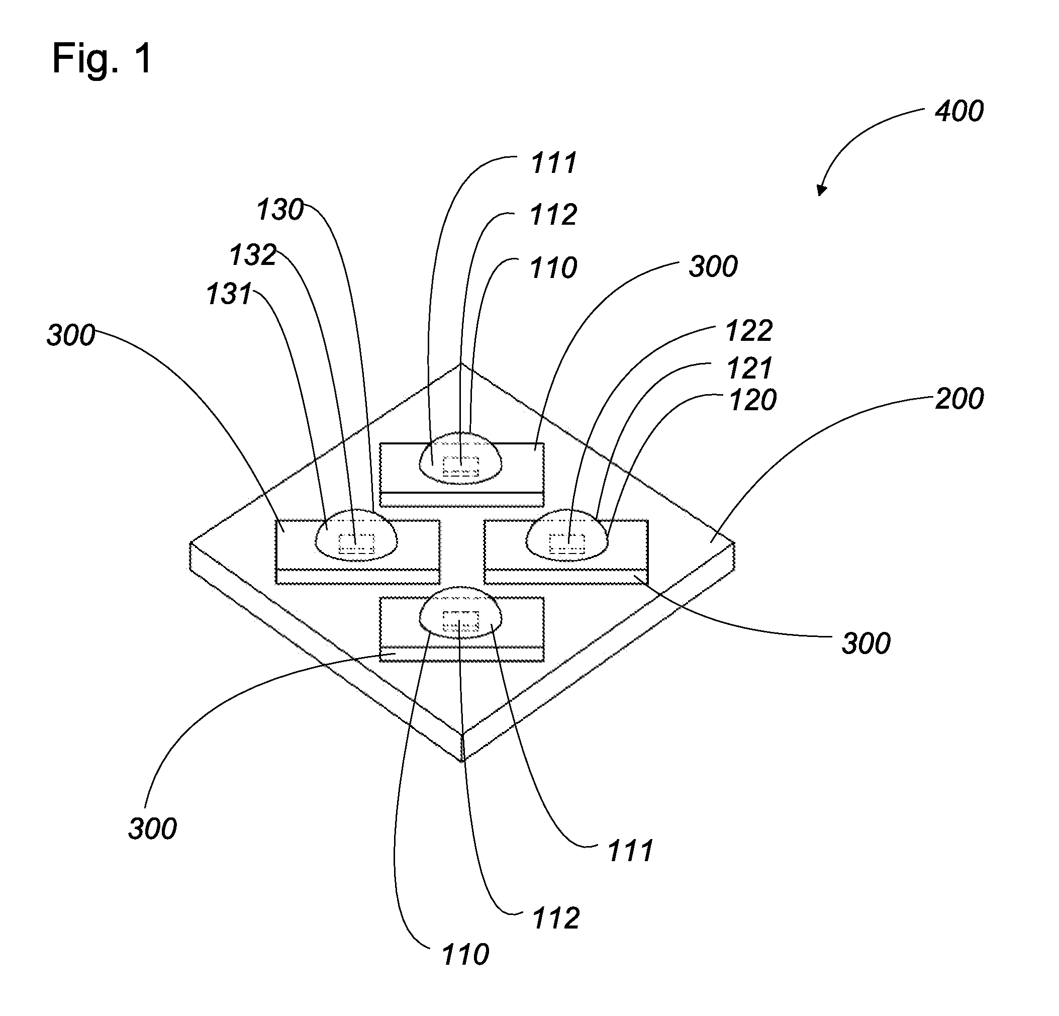
[0042]An LED lighting device of the first embodiment is explained with attached illustrations. FIG. 1 shows a schematic perspective view of the LED lighting device of the first embodiment. The LED lighting device 400 of the first embodiment comprises a circuit substrate 200, mounting substrates 300, a light emitting unit 110, a light emitting unit 120, and a light emitting unit 130. The light emitting unit 110, 120, and 130 are respectively mounted on the mounting substrates 300. The mounting substrates 300 are respectively mounted on the circuit substrate 200. The circuit substrate 200 is configured to receive an electrical power from outside, and is configured to supply the light emitting units 110, 120, and 130 with the electrical power. The light emitting units 110, 120, and 130 is configured to emit a light having a desired color. The light emitting units 110, 120, and 130 are configured to emit visible lights which have colors which are different from each other. The visible l...

second embodiment

[0062]A LED lighting device of the second embodiment is explained with attached illustrations. It is noted that the LED lighting device in the second embodiment comprises components same as the components of the first embodiment except for following features. Therefore, the same components are referred by same reference numerals. Therefore, explanations of the components explained in the first embodiment are omitted. Furthermore, in the illustrations, the components are represented by the reference numerals with suffix letter of “B”.

[0063]FIG. 6 shows a schematic perspective view of the LED lighting device 400B in the second embodiment. The LED lighting device 400B of the second embodiment comprises the circuit substrate 200B, the mounting substrate 300B, the light emitting units 110B and 120B, the blue LED chip 143B, and a light diffusion member 141B. The light emitting units 110B, the light emitting unit 120B, and the blue LED chip 143B is mounted on the mounting substrate 300B. T...

third embodiment

[0067]An LED lighting device of the third embodiment is explained with attached illustrations. The components same as that in the first embodiment is referred to as the same reference numerals. Therefore, explanations of the components explained in the first embodiment are omitted. In addition, the components are referred to as the reference numerals with a suffix letter of “C”.

[0068]FIG. 7 shows the top view of the LED lighting device 400C in the third embodiment. FIG. 8 (a) shows a schematic perspective view of the LED lighting device 400C of the third embodiment. FIG. 8 (b) shows a side cross sectional view of the LED lighting device 400C of the third embodiment. The LED lighting device comprises a base 510C, a package 500C, and the light emitting units 110C, 120C, and 130C. The package 500C is composed of the mounting substrate 300C and a sealing cap 520C.

[0069]The base 510C is made of a heat conductive material such as Al and Cu. The base 510C is formed to have a circular plate...


PUM


Abstract

An LED lighting device comprises a plurality of light emitting units which is configured to emit visible light having different colors which are mixed with each other to produce a white light. Each the light emitting units is composed of an LED chip and a phosphor. The LED chip is configured to generate light. The phosphor has a property of giving off a light of a predetermined color when the phosphor is excited by the light from the LED chip. The LED chip is selected from a group consisting of a blue LED chip, a UV LED chip, ad a violet LED chip. Each the phosphor is selected to give off the light of a predetermined color different from one another.

Description

TECHNICAL FIELD[0001]This invention relates to an LED lighting device which comprises a plurality of light emitting units. Each one of the light emitting units is configured to emit the light having a color which is different from colors of the lights which are emitted from the other light emitting units. Consequently, the LED lighting device in this invention is configured to produce light having a desired color.BACKGROUND ART[0002]PCT patent application publication No 03 / 019072A discloses a prior LED lighting device. The prior LED lighting device having a plurality of light emitting units on a circuit board. Each the light emitting unit is configured to emit the light having color which is different from the color of the light emitted from the other light emitting unit. The LED lighting device comprises a plurality of the light emitting units which is cooperative with each other to produce light having a desired color temperature. In this manner, the LED lighting device is configu...

Claims


Application Information

Patent Timeline
IPC IPC(8): H01L33/48F21V9/40H01L33/60
CPCF21K9/00H01L25/0753H01L33/60H05B33/0821H01L2924/0002H05B33/0857H01L2924/00H05B45/20H05B45/40
Inventor TANAKA, KENICHIROAKETA, TAKANORI
Owner PANASONIC CORP
Why Eureka
Try Eureka