Method and device for explosion forming

a technology of explosive forming and forming method, which is applied in the direction of explosives, electric/magnetic/electromagnetic heating, weapons, etc., can solve the problems of not being accepted in the practice of mass production, shortest possible setup time must be repeatedly achieved, etc., and achieve rapid and proper positioning and increase the effect of device efficiency

Active Publication Date: 2010-08-19
COSMA ENG EURO AG
View PDF33 Cites 2 Cited by
  • Summary
  • Abstract
  • Description
  • Claims
  • Application Information

AI Technical Summary

Benefits of technology

[0006]The underlying task of the invention is to improve a method, as well as device, of the generic type just mentioned, so that an ignition mechanism that is technically simple to handle is produced with short setup times, which permits the most precise possible ignition of the explosive with time-repeatable accuracy.

Problems solved by technology

On the one hand, the die and the ignition mechanism must be suitable to initiate the explosion in targeted fashion and withstand the high loads occurring during the explosion, and, on the other hand, good forming results with the shortest possible setup times must be repeatedly achieved.
Both methods are particularly suitable for individual part manufacture and have not gained acceptance in practice for mass production.

Method used


Image

  • Method and device for explosion forming
  • Method and device for explosion forming
  • Method and device for explosion forming

Examples


first embodiment

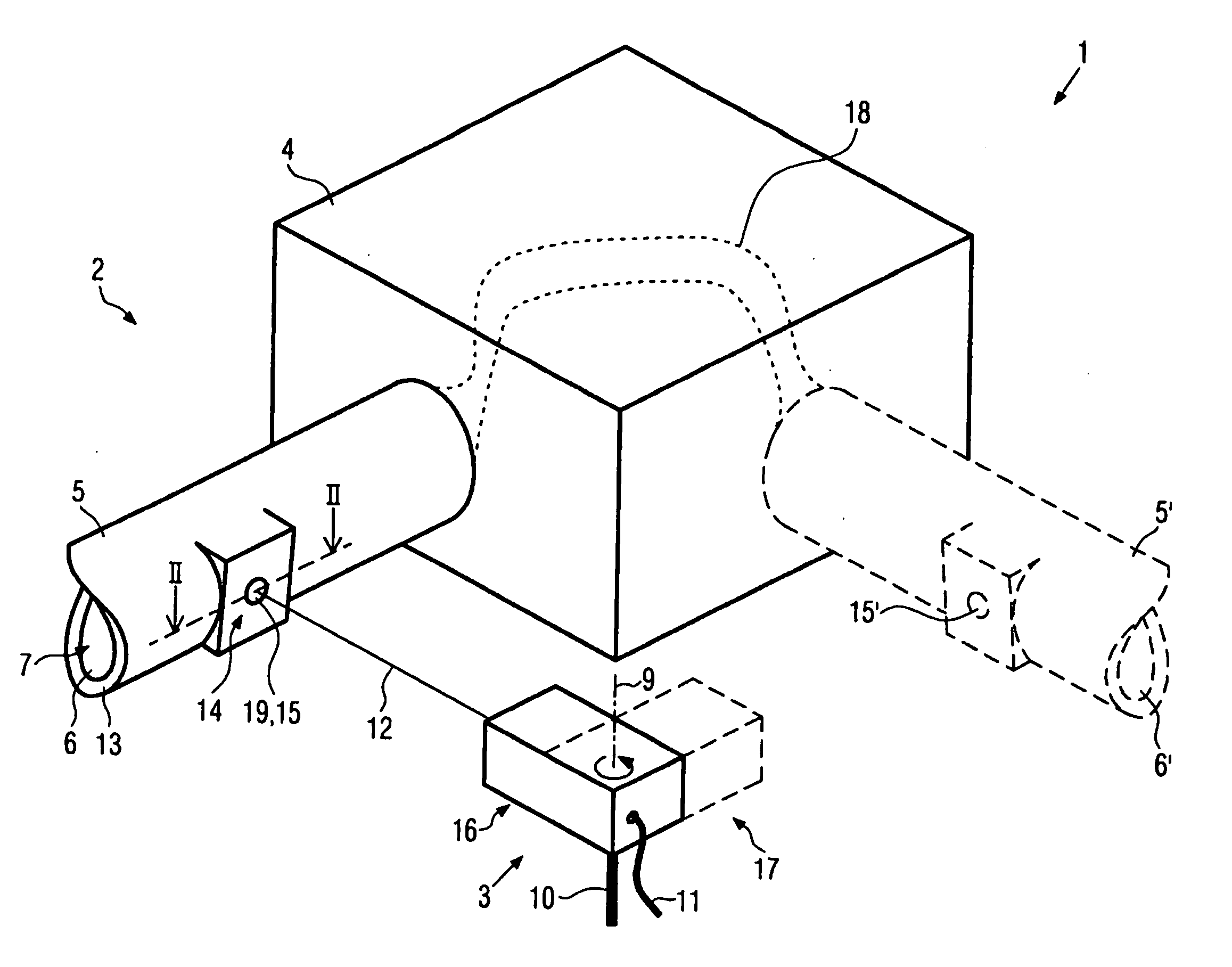
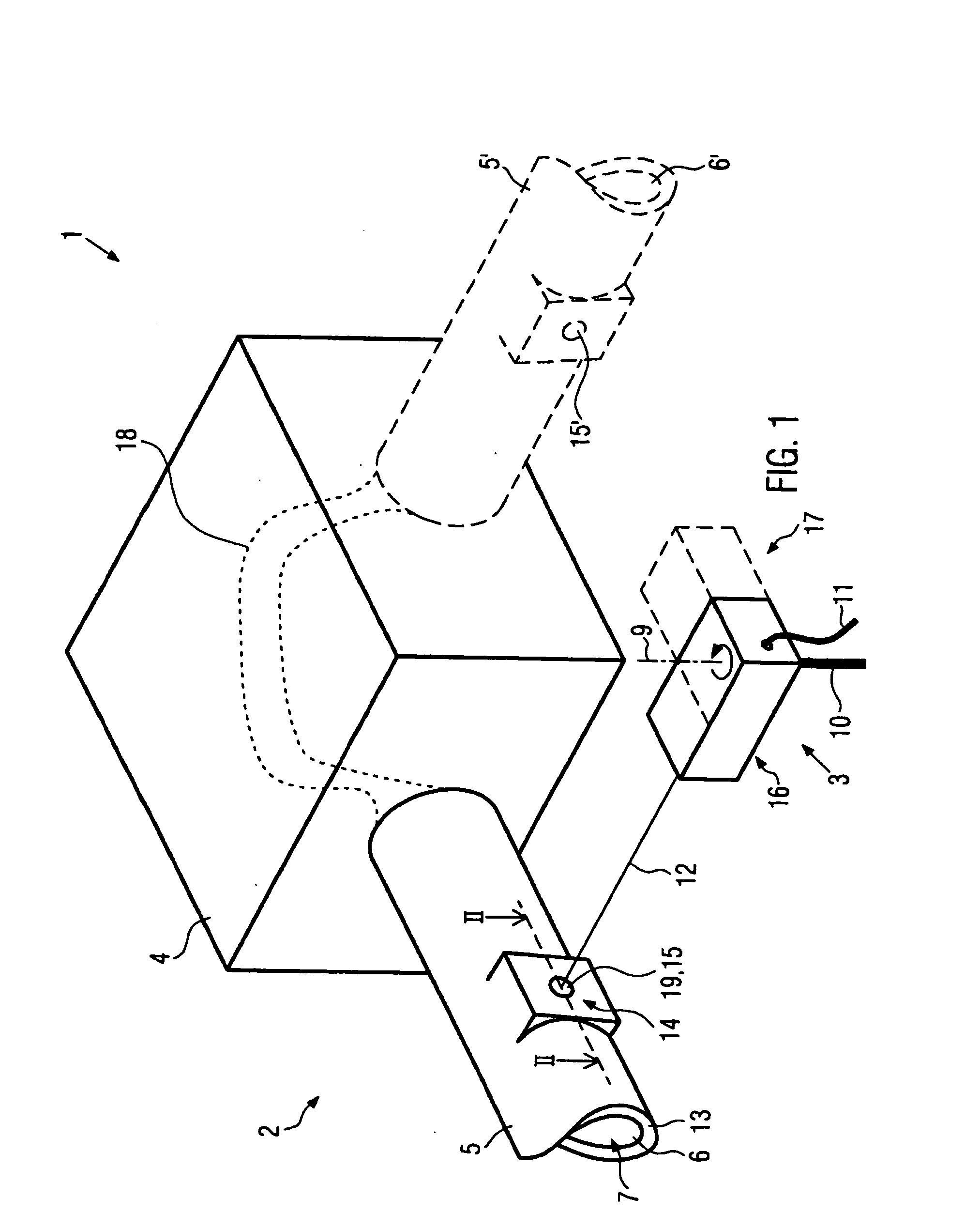
[0042]FIG. 1 shows a device for explosive forming according to the invention. The device 1 has a die 2 and an energy beam generator 3.

[0043]The die 2 in this embodiment of the invention is multipart and has a forming device 4 and an ignition tube 5. In the forming device 4, a work piece 18, indicated by a dotted line, is arranged here. In the interior of ignition tube 5, an ignition chamber 6 is provided. An explosive medium 7 is situated in it.

[0044]An explosive gas mixture, oxyhydrogen gas, is provided as explosive medium 7 in this embodiment, which can be introduced to ignition chamber 6 via connection 8. In other embodiments of the invention, however, other explosives can also be used in gaseous, liquid or solid form. Connection 8 is then designed according to the explosive as a gas, liquid or solid connection.

[0045]The energy beam generator 3 can optionally generate an energy beam 12 and, in this embodiment, is a laser device, which is mounted on a foot 10 to rotate around its ...

second embodiment

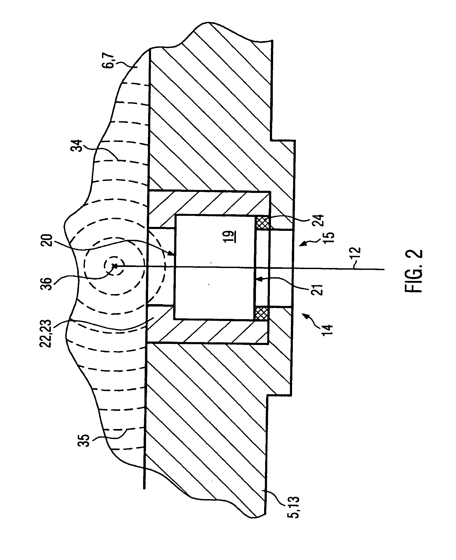
[0058]FIG. 3a shows a schematic view of a device according to the invention. The reference numbers used in FIG. 3a denote the same parts as in FIGS. 1 and 2, so that the description of FIGS. 1 and 2 is referred to in this respect. The device 1 depicted in FIG. 3a has several dies 2 and several energy beam generators or laser devices 3. The design of these devices corresponds to the design shown in FIGS. 1 and 2 and repeatedly occurring same components are therefore provided with the suffix a, b, etc.

[0059]The device 1 here has four dies 2a to 2d and four laser devices 3a to 3d. The dies 2a to 2d are arranged approximately in a circle 30, indicated here with a dotted line. The laser devices 3a to 3d are also arranged approximately in a circle 31 that lies approximately concentric within circle 30. The laser devices 3a to 3d are arranged in relation to dies 2a to 2d, so that one of the laser beams 12a to 12d penetrates through transparent medium 15 into one of the dies 3a to 3d in ign...

third embodiment

[0061]FIG. 3b shows a schematic view of a device according to the invention. The reference numbers used in FIGS. 1 and 2 denote the same parts as in FIG. 3b, so that the description of FIGS. 1 and 2 is referred to in this respect. The device 1 depicted in FIG. 3a has several dies 2 and energy or laser beam generators 3. The design of the individual dies 2a to 2d and of the energy beam generator 3 corresponds to the die 2 and energy beam generator 3 depicted in FIGS. 1 and 2.

[0062]The device 1 here additionally has a deflection device 25 for the energy or laser beam 12. In this case, the deflection device 25 is a mirror arrangement. It has a central polyhedral element 27 and several, in this case three, additional mirror elements 28. The surfaces of the central element 27 also have mirrors 29. In this embodiment of the invention, four surfaces of the central element 27 are provided with mirrors 29. At least of the mirrors 29 can then be partially transparent to the energy or laser be...


PUM

PropertyMeasurementUnit
thicknessaaaaaaaaaa
thicknessaaaaaaaaaa
thicknessaaaaaaaaaa

Abstract

With the invention, a method and a device for explosive forming of work pieces, in which at least one work piece is arranged in at least one die and there deformed by means of an explosive to be ignited, is to be improved, in that an ignition mechanism that is technically easy to handle is produced with the shortest possible setup times, which permits the most precise possible ignition of the explosive with time-repeatable accuracy. This task is solved by a method and device, in which at least one work piece is arranged in at least one die and deformed there by means of an explosive being ignited, in which the explosive is ignited by means of at least one energy beam.

Description

CROSS-REFERENCE TO RELATED APPLICATIONS[0001]This application claims priority from German Patent Application Serial No. 102006037742.7 filed on Aug. 11, 2006, entitled “Verfahren and Vorrichtung zum Explosionsumformen” (Method and Device for Explosive Forming), the disclosure of which is incorporated herein by reference for all purposes.FIELD OF THE INVENTION[0002]The invention concerns a method and a device for explosive forming.BACKGROUND OF THE INVENTION[0003]During explosive forming, a work piece is arranged in a die and deformed by ignition of an explosive, for example, a gas mixture. The explosive is generally introduced to the die, and also ignited here. Two problems are then posed. On the one hand, the die and the ignition mechanism must be suitable to initiate the explosion in targeted fashion and withstand the high loads occurring during the explosion, and, on the other hand, good forming results with the shortest possible setup times must be repeatedly achieved.[0004]In a...

Claims


Application Information

Patent Timeline
Patent Type & Authority Applications(United States)
IPC IPC(8): B21D26/08
CPCB21D26/08
Inventor ZAK, ALEXANDERSTRANZ, ANDREAS
Owner COSMA ENG EURO AG
Why Eureka
Try Eureka