
Magnetic gear

Active Publication Date: 2010-08-19
MAGNOMATICS LTD
View PDF6 Cites 16 Cited by
  • Summary
  • Abstract
  • Description
  • Claims
  • Application Information

AI Technical Summary

Benefits of technology

[0009]Advantageously, the magnetic gears according to embodiments of the present invention exhibit significant advantages, in terms of simplicity and torque density, especially when higher gear ratios are required as compared to the prior art.

Problems solved by technology

However, white such a high-speed electrical machine in conjunction with a mechanical gearbox allows high system torque densities to be realised, such mechanical gearboxes usually require lubrication and cooling.
Furthermore, reliability can also be a significant issue.
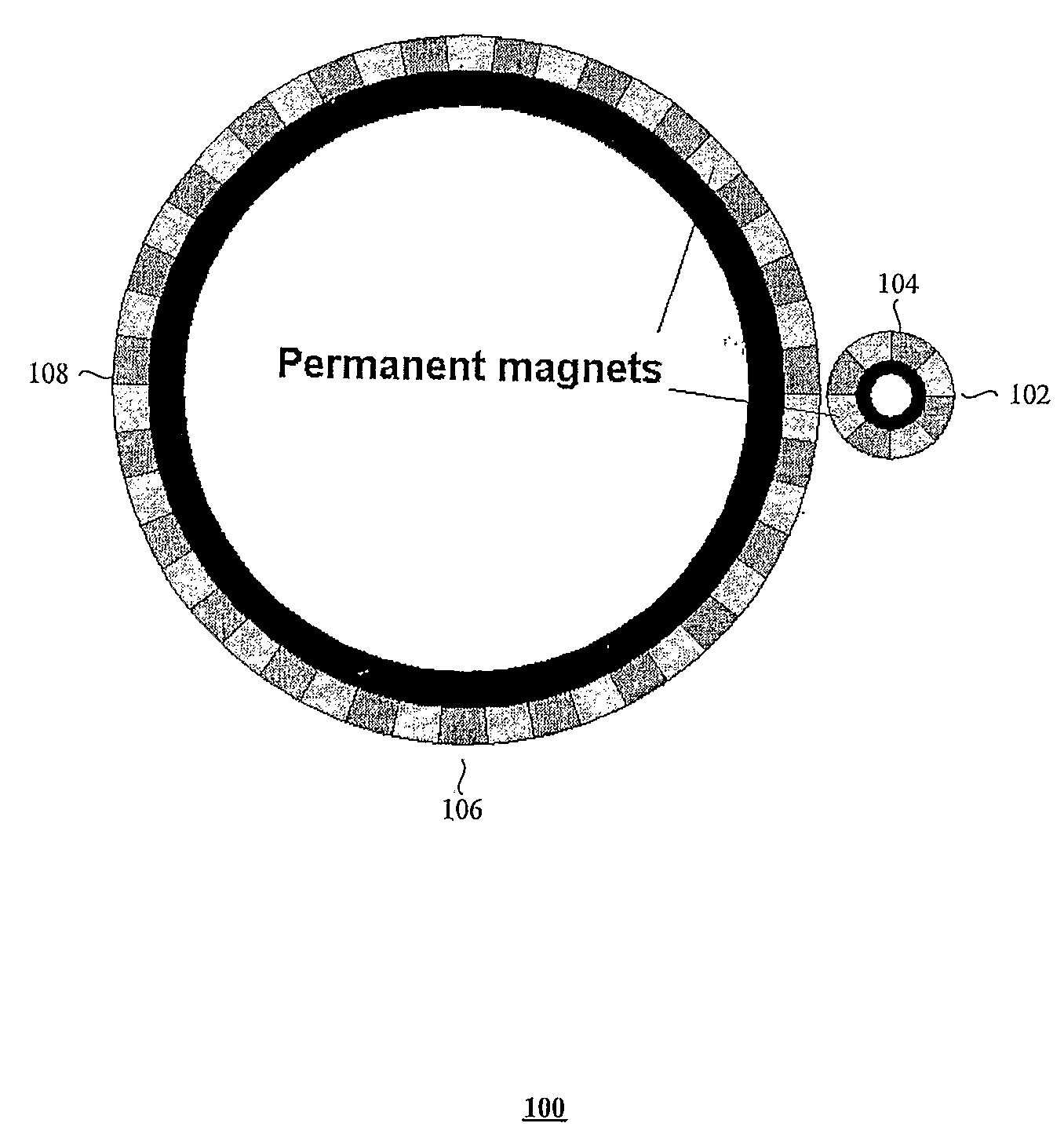
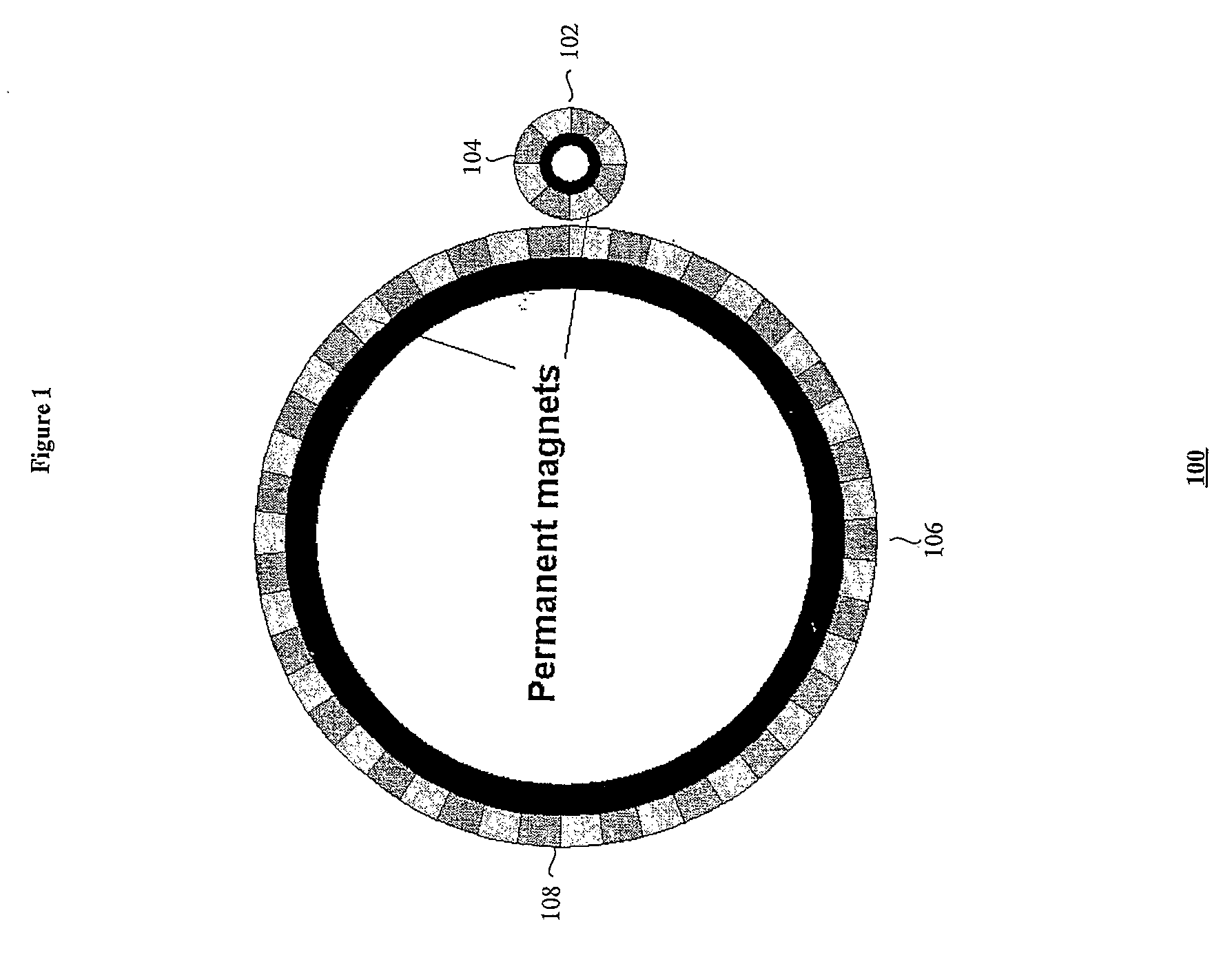
A significant disadvantage of the magnetic gear 100 shown in FIG. 1 is that the topology suffers from a very poor utilisation of the permanent magnets since very few of the permanent magnets simultaneously contribute to torque transmission at any given time.
The very poor torque transmission capability has limited the use of magnetic gearing.
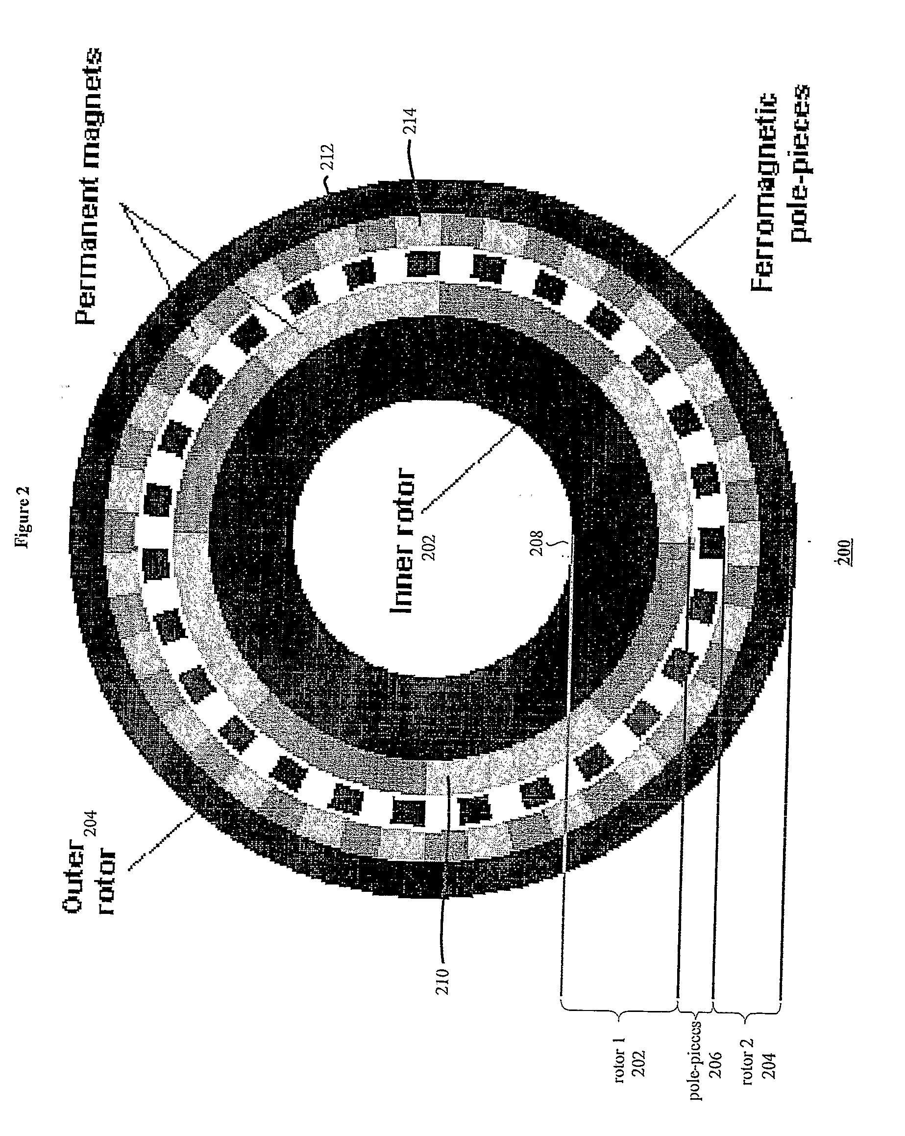
However, the magnetic gear topology shown in FIG. 2 has the disadvantages that it is unsuitable for high gear ratios, it is relatively complex and has an unfavourable torque density especially when higher gear ratios are required.

Method used


Image

  • Magnetic gear
  • Magnetic gear
  • Magnetic gear

Examples


Embodiment Construction

[0008]Accordingly, a first aspect of embodiment of the present invention provides a magnetic gear comprising first and second moveable members having associated first and second pluralities of permanent magnets respectively arranged such that the first and second pluralities of permanent magnets are separated by a varying distance that, in response to relative movement of the first and second moveable members, magnetically couples the first and second pluralities of permanent magnets in a geared manner via a common magnetic harmonic generated as a consequence of the relative movement.

[0009]Advantageously, the magnetic gears according to embodiments of the present invention exhibit significant advantages, in terms of simplicity and torque density, especially when higher gear ratios are required as compared to the prior art.

[0010]Other embodiments are described below and claimed in the claims.

BRIEF DESCRIPTION OF THE DRAWINGS

[0011]Embodiments of the present invention will now be descr...


PUM


Abstract

Embodiments of the present invention relate to magnetic gears comprising a pair of rotors magnetically coupled in a geared manner via a magnetic space harmonic generated as a consequence of varying an air gap between sets of permanent magnets.

Description

FIELD OF THE INVENTION[0001]Embodiments of the present invention relate to magnetic gears.BACKGROUND TO THE INVENTION[0002]Mechanical gearboxes are extensively used to match the operating speed of prime-movers to the requirements of their loads for both increasing rotational speed such as, for example, in a wind-powered generator or reducing rotational speed such as, for example, in an electric-ship propulsion arrangement. It is usually more cost and weight effective to employ a high-speed electrical machine in conjunction with a mechanical gearbox to achieve requisite speed and torque characteristics. However, white such a high-speed electrical machine in conjunction with a mechanical gearbox allows high system torque densities to be realised, such mechanical gearboxes usually require lubrication and cooling. Furthermore, reliability can also be a significant issue. Consequently, direct drive electrical machines are employed in applications where a mechanical gearbox cannot be used...

Claims


Application Information

Patent Timeline
IPC IPC(8): H02K49/10
CPCH02K49/102F16H49/001
Inventor ATALLAH, KAIS
Owner MAGNOMATICS LTD
Learn More