Speed increase gear drive mechanism of speed increase device of circulation type forward and backward turning and variable speed vacuum compressor

A vacuum compressor and speed-increasing gear technology, applied in the field of vacuum compressors, can solve the problems that the jaw clutch is easy to disengage the transmission device, restrict the efficiency of the vacuum compressor's vacuuming and compression functions, and achieve compact structure, The effect of reasonable design and high speed-up transmission ratio

Inactive Publication Date: 2014-03-26
兆盈建筑劳务(大连)有限公司
View PDF6 Cites 1 Cited by
  • Summary
  • Abstract
  • Description
  • Claims
  • Application Information

AI Technical Summary

Problems solved by technology

Although the screw reciprocating vacuum compressor has improved compared with the structure of the above-mentioned reciprocating vacuum pump and the reciprocating compressor, there are still some shortcomings and deficiencies in its transmission device. It is easy to disengage and its transmission device cannot work normally under high-speed conditions, which restricts the efficiency of the vacuuming and compression functions of the vacuum compressor; The forward and reverse variable speed vacuum compressor is a circular forward and reverse variable speed vacuum compressor. The variable speed transmission device includes a reduction device, a forward and reverse gear synchronous drive assembly, a forward and reverse reversing device and a speed increasing device, among which

Method used


Image

  • Speed increase gear drive mechanism of speed increase device of circulation type forward and backward turning and variable speed vacuum compressor
  • Speed increase gear drive mechanism of speed increase device of circulation type forward and backward turning and variable speed vacuum compressor
  • Speed increase gear drive mechanism of speed increase device of circulation type forward and backward turning and variable speed vacuum compressor

Examples


Embodiment Construction

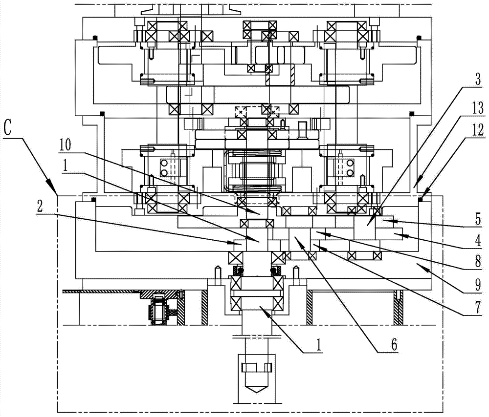
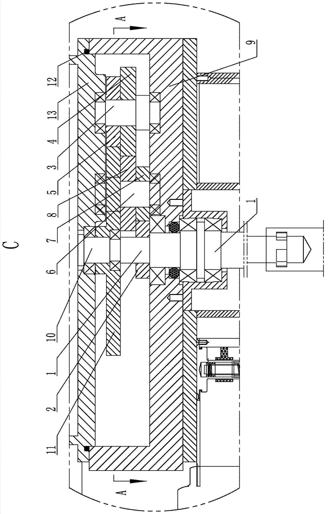
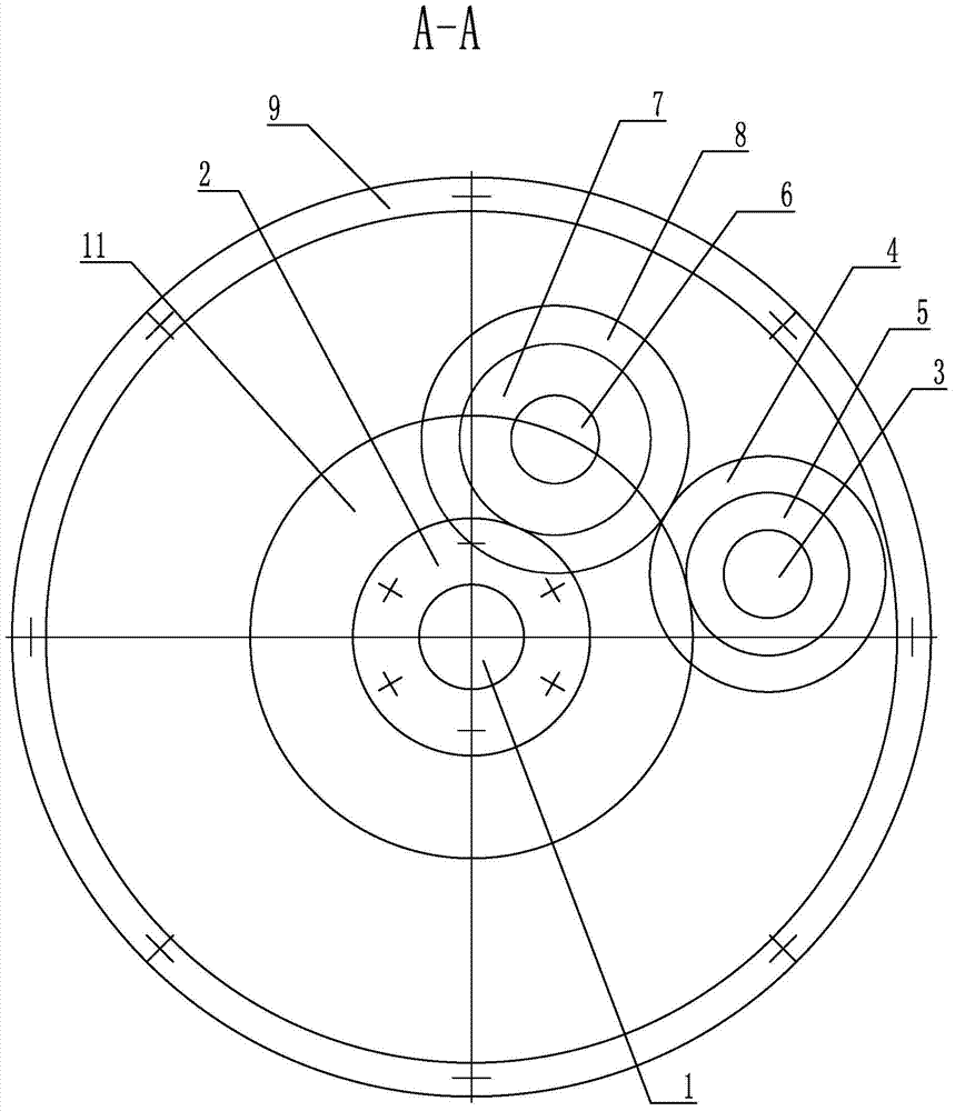
[0015] figure 1 , 2 Shown in , 3 is the specific embodiment of the present invention, and it is the speed-increasing gear transmission mechanism of the speed-increasing device of the vacuum compressor of circulating forward and reverse variable-speed, including output shaft 1, output gear 2, change-to-change main shaft 10, change-to-change Gear 11, speed-up box 9 and change direction box are characterized in that: on the output gear 2 of output shaft 1, speed-up gear transmission mechanism is installed, and described speed-up gear transmission mechanism consists of first transition gear shaft 3, first transition gear 4. The second transition gear 5, the second transition gear shaft 6, the third transition gear 7 and the D transition gear 8 are composed, the bottom end of the first transition gear shaft 3 is supported in the bottom surface of the speed-up box 9 by bearings, and the first transition gear The top of shaft 3 is supported in the boss on the top of speed-up box 9 b...


PUM


Abstract

The invention belongs to a vacuum compressor, and particularly relates to a speed increase gear drive mechanism of a speed increase device of a circulation type forward and backward turning and variable speed vacuum compressor. The speed increase gear drive mechanism comprises an output shaft, an output gear, a main turning shaft, a turning gear, a speed increase gearbox and a turning case, and is characterized in that a speed increase gear drive mechanism body is installed on the output gear of the output shaft and composed of a first transition gear shaft, a first transition gear, a second transition gear, a second transition gear shaft, a third transition gear and a fourth transition gear, the first transition gear shaft is provided with the first transition gear and the second transition gear sequentially, the third transition gear and the fourth transition gear are sequentially installed on the second transition gear shaft, the output gear is meshed with the third transition gear, the fourth transition gear is meshed with the first transition gear, and the second transition gear is meshed with the turning gear of the main turning shaft. The speed increase gear drive mechanism is reasonable in design and compact in structure, and has the advantages of being high in speed increase transmission ratio, stable and reliable in transmission performance, capable of improving the vacuum pumping efficiency and compression efficiency of the vacuum compressor, and the like.

Description

technical field [0001] The invention belongs to vacuum compressors, in particular to a speed-increasing gear transmission mechanism of a cycle-type forward and reverse variable-speed vacuum compressor speed-increasing device. Background technique [0002] At present, in mechanical products, such as mechanical transmission devices of reciprocating vacuum pumps and reciprocating compressors, most of its structures adopt motors, belt transmissions to drive crankshafts and eccentric wheel-type transmission mechanisms. The reciprocating motion is realized by using the slider and the connecting rod to cooperate to push the piston. Due to the restriction of the above-mentioned transmission mode, the distribution form of the cylinder body can only be V-shaped, fan-shaped or parallel twin-cylinder type. Due to the periodic inflection point or dead point in the transmission of the crankshaft and the eccentric wheel—that is, the dead point where the output torque is "0"; the transmissi...

Claims


Application Information

Patent Timeline
Patent Type & Authority Applications(China)
IPC IPC(8): F04B35/01F04B37/14
Inventor 王久祥张庆鹏王海涛
Owner 兆盈建筑劳务(大连)有限公司
Why Eureka
Try Eureka