Method of controlling a power transfer system and power transfer system

a power transfer system and power transfer technology, applied in the direction of transmission, electric vehicles, transportation and packaging, etc., can solve the problems of flammable gas environment, device use in flammable gas environment, and the cost and inconvenience of regularly having to purchase new (not rechargeable) cells for users, etc., to achieve optimal charging operation

Active Publication Date: 2010-08-19
NXP BV
View PDF5 Cites 124 Cited by
  • Summary
  • Abstract
  • Description
  • Claims
  • Application Information

AI Technical Summary

Benefits of technology

[0014]It is therefore an object of the present invention, to provide a method of controlling a power transfer device as well as the power transfer device which ensures optimized charging operation even if a portable device suffers from a completely exhausted or dead battery power source.

Problems solved by technology

Portable devices, and in particular electronic equipment, such as mobile phones or small hand-held computers, any mobile and wireless devices include secondary power cells for power supply which are usually provided in the form of rechargeable power cells (rechargeable batteries) saving the user the costs and the inconvenience of regularly having to purchase new (not rechargeable) cells.
Conventional adaptors or chargers exhibit a number of problems when used for recharging secondary cells of any arbitrary portable device.
The adaptors and chargers usually require the users to plug a connector into the device, and the devices should better not be used in wet environment due to the possibility of corroding or shorting out the contacts, and also such devices cannot be used in flammable gaseous environment due to the possibility of creating electrical sparks.
The arrangements as mentioned above, however, lead to a non-uniform flux distribution of the magnetic field so that the charging effectivity is largely dependent from the correct placement of the portable device on the inductive charger.
That is, when the portable device is placed on the charging module which constitutes a docking station with integrated inductive link for power transfer, this also poses several other problems.
Moreover, every docking station or every charging module needs to be plugged into sockets of a mains power supply, and when several docking stations are used together, they take up space in plug strips and create a messy and confusing tangle of wires.
In many cases portable or mobile devices to be charged must be placed into a stand, usually one device per one docking station, causing inconvenience for the user.
This sets limitations for the user interface of the device (position on the desk, horizontal and axial viewing angle to the display means of the device).
Specifically, when the portable device is used in an extensive manner and the battery thereof is completely exhausted or when the battery is damaged and cannot provide any suitable power to power-up the portable device, it is necessary to charge the battery power source of the portable device in an appropriate manner.
It may also occur that the battery is not correctly mounted to the portable device and cannot power the portable device.
When the portable device suffers from such a “dead battery condition” or a corresponding malfunction it is difficult to charge the battery power source of such a portable device as the correct or optimized charging power cannot be determined when the portable device suffering from the dead battery condition is placed on the charging module (charging pad) of a power transfer device.

Method used


Image

  • Method of controlling a power transfer system and power transfer system
  • Method of controlling a power transfer system and power transfer system
  • Method of controlling a power transfer system and power transfer system

Examples


Embodiment Construction

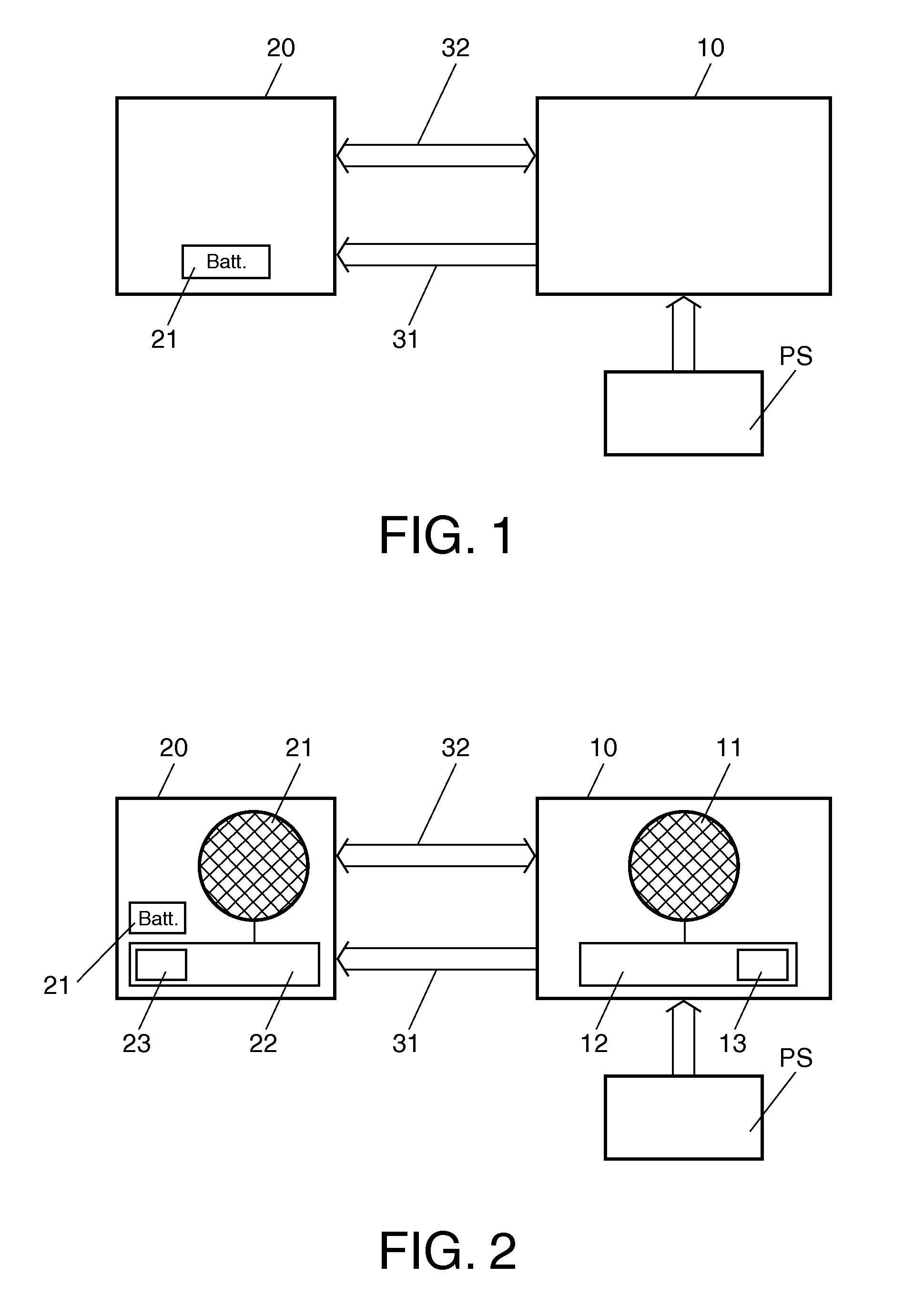
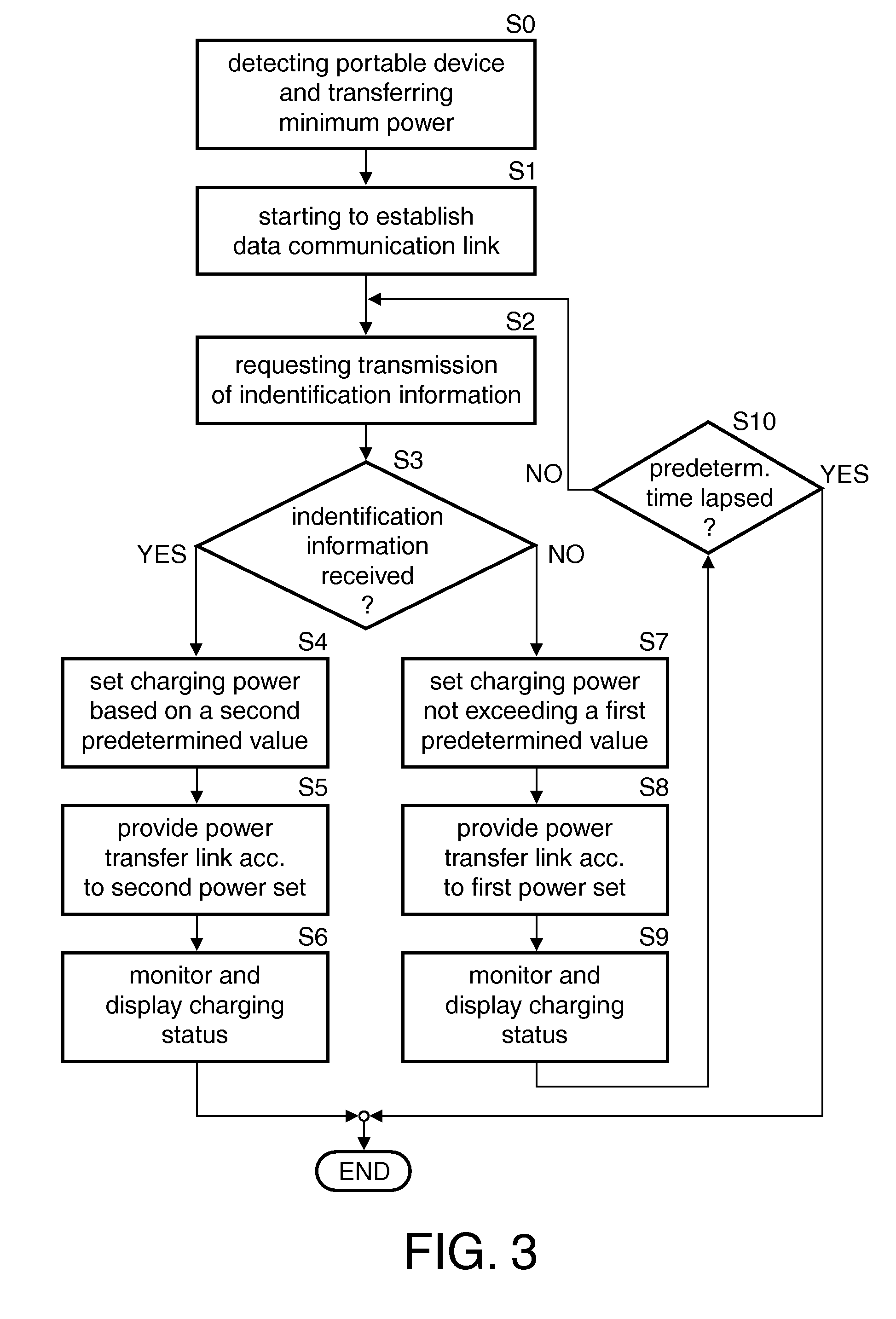
[0030]A first embodiment of the method of controlling the power transfer system as well as of the power transfer system according to the present invention is now described in detail in conjunction with FIGS. 1 to 3.

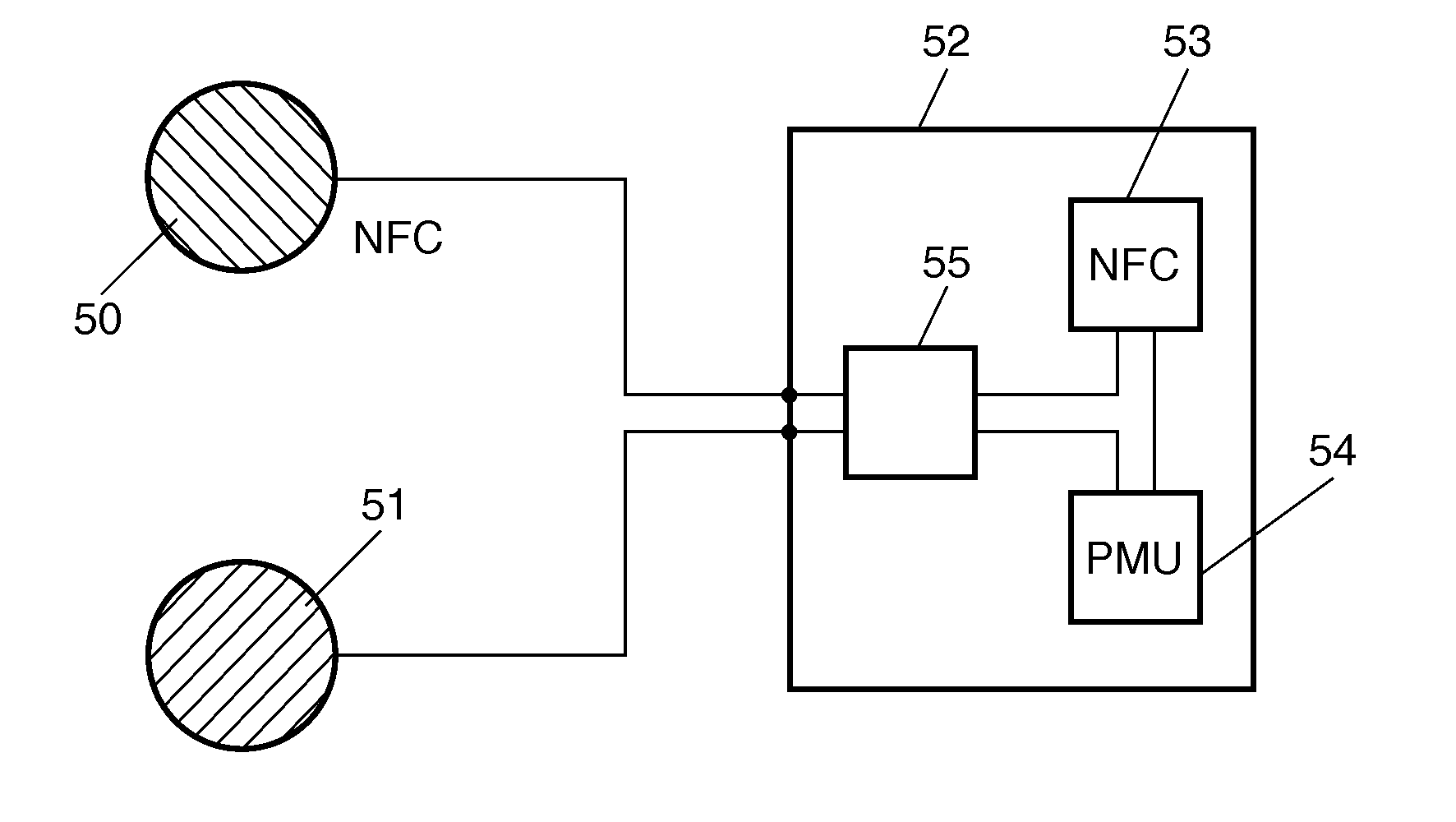
[0031]FIG. 1 shows the basic arrangement of the power transfer system of the present invention in the form of a schematic diagram in which a power transfer device 10 is provided as a charging device (charging pad) for a portable device 20. The at least one portable device 20 includes a rechargeable battery (rechargeable cell) as the battery power source 21 thereof which is recharged by a power delivered from or transferred by the power transfer device 10. The portable device 20 which includes the battery power source 21 is powered by this rechargeable battery.

[0032]The power transfer device 10 receives from a mains power supply network PS which is usually provided in the form of a public power supply network power for its own operation and for transferring a suitable powe...


PUM


Abstract

The present invention relates to a power transfer system which comprises a power transfer device (10) as well as at least one portable device (20), and to a method of controlling the power transfer system specifically in case of a dead battery condition of a battery (21) of the portable device (20). The power transfer device (10) for wireless charging of the battery (21) arranged in the portable device (20) and the power transfer device (10) each comprise a near field communication functionality for data communication by a data communication link (32) between the devices. The method includes a step of starting to establish the data communication link (32) between the power transfer device (10) and the portable device (20). When the establishment of the data communication link (32) is started, the power transfer device (10) requests the portable device (20) to transmit an identification information via the data communication link (32) to the power transfer device (10). It is then detected whether the identification information of the portable device (20) is received by the power transfer device (10). Depending upon whether the identification information is received a setting is performed for setting a charging power to be transferred from the power transfer device (10) to the portable device (20). The setting provides a reduced charging power not exceeding a first predetermined value when the identification information is not received. Depending upon this setting a power transfer link (31) is established by the power transfer device (10), and the charging power not exceeding the first predetermined value is transferred to the portable device (20) so that the portable device (20) can be powered by this transferred power to enable data communication and to charge the battery (21).

Description

FIELD OF THE INVENTION[0001]The present invention relates to a method of controlling a power transfer system for transferring electric power from a power supply device to a portable device, and to the power transfer system.BACKGROUND OF THE INVENTION[0002]Portable devices, and in particular electronic equipment, such as mobile phones or small hand-held computers, any mobile and wireless devices include secondary power cells for power supply which are usually provided in the form of rechargeable power cells (rechargeable batteries) saving the user the costs and the inconvenience of regularly having to purchase new (not rechargeable) cells. Rechargeable cells are preferred due to economical and environmental reasons.[0003]A charging operation of the rechargeable cells can be performed by using an adaptor or charger which takes power from a public electrical power network (mains power supply) or other adequate sources of power. The adaptor or charger connected to the mains power supply...

Claims


Application Information

Patent Timeline
Patent Type & Authority Applications(United States)
IPC IPC(8): H02J7/00
CPCH02J7/022H02J7/025H04B5/0037H02J50/80H02J50/10H02J7/02H02J2207/20H02J50/40
Inventor PIJNENBURG, REMCO H. W.MOTTE, BRUNDSCHOLTENS, PETER C. S.
Owner NXP BV
Why Eureka
Try Eureka