Eureka AIR delivers breakthrough ideas for toughest innovation challenges, trusted by R&D personnel around the world.

Light Guiding Device and Thin Display Comprising the Same

a technology of light guiding and thin display, which is applied in the field of display, can solve the problems of visual fatigue, difficult to integrate the two different light sources in this solution, and large angle light leakag

Inactive Publication Date: 2010-08-19
AU OPTRONICS CORP
View PDF5 Cites 25 Cited by
  • Summary
  • Abstract
  • Description
  • Claims
  • Application Information

AI Technical Summary

Problems solved by technology

When a user fixates on such an LCD from above the display for a long time, visual fatigue tends to result.
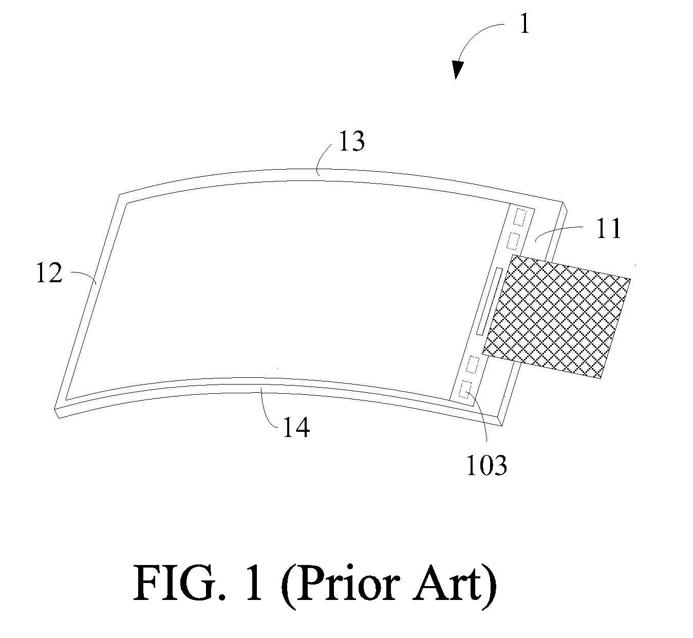
However, a problem with such an arc-shaped display 1 is that light from LEDs 103 disposed along the side 11 can only propagate linearly instead of taking turns to follow the arc curvature of a light guiding plate.
This leads to nonuniformity in the distribution of light on the light guiding plate, thereby resulting in light leakage at large angles.
However, it is difficult to integrate the two different light sources in this solution.

Method used


Image

  • Light Guiding Device and Thin Display Comprising the Same
  • Light Guiding Device and Thin Display Comprising the Same
  • Light Guiding Device and Thin Display Comprising the Same

Examples


Embodiment Construction

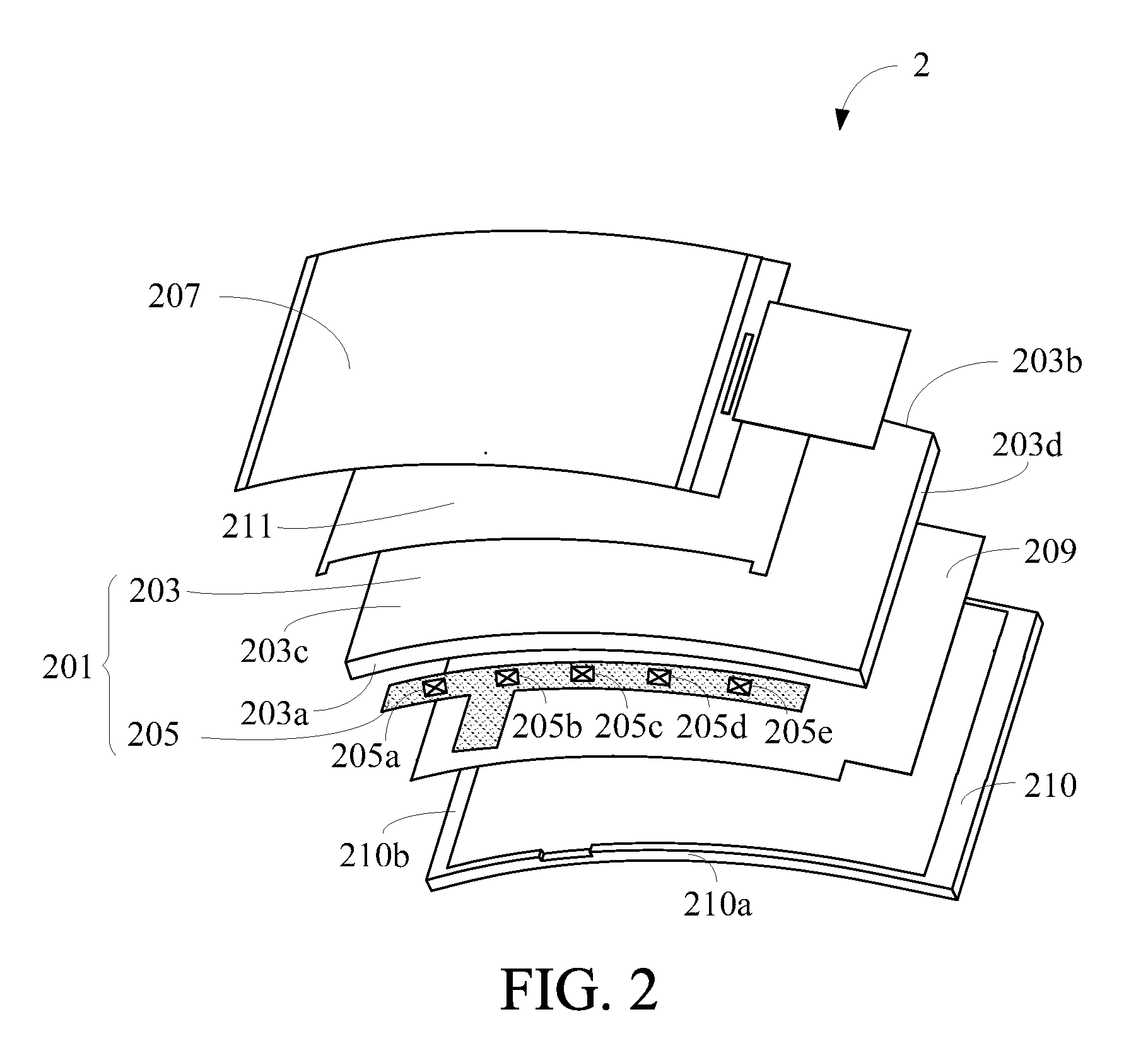
[0018]FIG. 2 illustrates a schematic view of a thin display 2 according to the first embodiment of the present invention. The thin display 2 comprises a light guiding device 201, a panel 207, a reflection film 209, a frame 210 and an optical thin film 211. The thin display 2 in this embodiment has an arc-shaped outline; however, the arc curvature shown in this figure is only for purposes of illustration but not to limit this invention.

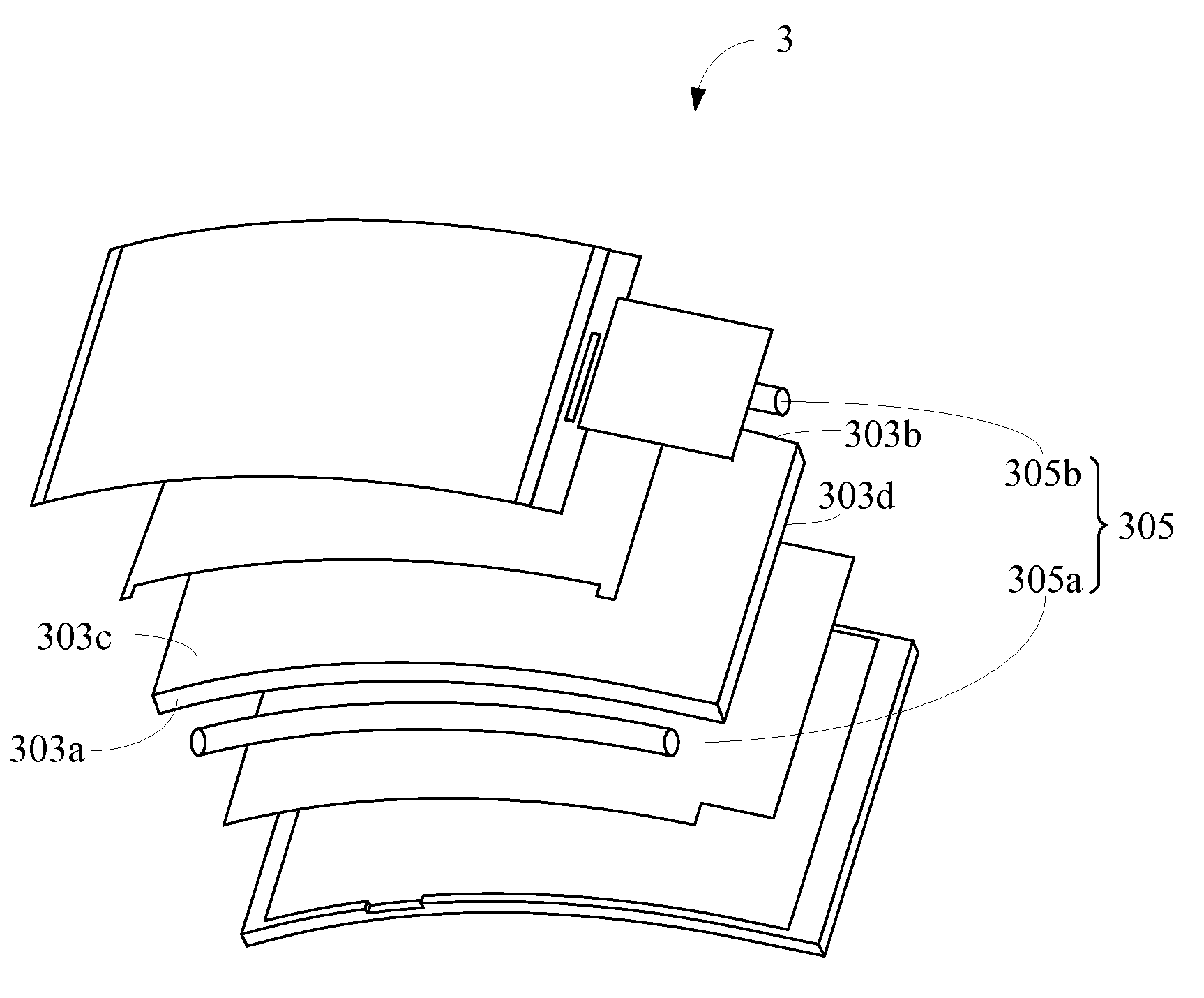
[0019]The frame 210 has two opposite arc-shaped frames 210a and two opposite side frames 210b, and the arc-shaped frames 210a and the side frames 210b are joined together. The light guiding device 201 disposed in the frame 210 has a light guiding plate 203 and a light source device 205. The light guiding plate 203 comprises a first arc-shaped plane 203a, a second arc-shaped plane 203b, an upper curve surface 203c and a lower curve surface 203d. Two edges of each of the upper curve surface 203c and the lower curve surface 203d are connected with the fir...


PUM


Abstract

A light guiding device and a thin display comprising the same are disclosed. The thin display comprises a light guiding device, a panel, and a frame. The frame comprises two arc-shaped frames opposite each other and two side frames opposite each other. The light guiding device comprises a light guiding plate and a light source device. The light guiding plate comprises an upper curve surface, a lower curve surface, a first arc-shaped plane, and a second arc-shaped plane. Two edges of each of the upper and the lower curve surfaces are connected with the first arc-shaped plane and the second arc-shaped plane respectively. The light source device is disposed between one of the first and the second arc-shaped planes and one of two arc-shaped frames. The panel is disposed in the frame and above the light guiding device.

Description

[0001]This application claims the benefit from the priority of Taiwan Patent Application No. 098104945 filed on Feb. 17, 2009, the disclosure of which is incorporated by reference herein in their entirety.CROSS-REFERENCES TO RELATED APPLICATIONS[0002]Not applicable.BACKGROUND OF THE INVENTION[0003]1. Field of the Invention[0004]The present invention relates to a display, and more particularly, to an arc-shaped display.[0005]2. Descriptions of the Related Art[0006]Liquid crystal displays (LCDs) have gradually replaced conventional cathode ray tube (CRT) displays due to its advantages such as a low profile, light weight, low power consumption and low radiation.[0007]Currently, LCDs generally have an upright outline. When a user fixates on such an LCD from above the display for a long time, visual fatigue tends to result. In view of this, LCDs with arc-shaped surfaces have been designed by some manufacturers to improve this problem.[0008]FIG. 1 shows an arc-shaped display 1, which has ...

Claims


Application Information

Patent Timeline
Patent Type & Authority Applications(United States)
IPC IPC(8): F21V8/00F21K99/00
CPCG02B6/002G02B6/0068G02B6/0045
Inventor KUO, HAN-PINGSU, CHENG-YI
Owner AU OPTRONICS CORP
Why Eureka
Eureka Blog
Learn More